Pressure-balanced electric motor wheel drive for a pipeline tractor

a technology of electric motor and hydraulic motor, which is applied in the direction of railway components, railway tracks, roads, etc., can solve the problems of pipeline tractor devices that cannot be driven by conventional means, can not be operated reliably or reliably, and lose traction of self-propelled pipeline tractor devices, so as to reduce the susceptibility of internal motors, prevent loss of traction, and contribute to the overall durability and reliability of pipeline tractor devices

Inactive Publication Date: 2008-10-09
GENERAL ELECTRIC CO
View PDF21 Cites 67 Cited by
  • Summary
  • Abstract
  • Description
  • Claims
  • Application Information

AI Technical Summary

Benefits of technology

[0004]Each traction drive wheel assembly includes a compact internal brushless DC electric motor along with a freewheeling Sprague-type clutch mechanism, a harmonic drive reducer gear assembly and other conventional motor and wheel components (e.g., bearings and races, seals, etc.). All of the drive motor components are integrated into a compact self-contained wheel housing and all of the drive wheels are powered from a single on-board battery. Each drive wheel of the tractor is individually controlled via a separate motor drive controller circuit mounted on-board the tractor. The use of separate motor drive controller circuits enables each drive wheel to produce a wide range of torque while individually controlling wheel speed to prevent loss of traction.
[0005]Each drive wheel assembly is oil-filled and the dc motor, harmonic drive gear and free-wheeling clutch components are continuously maintained in an oil bath environment which provides both lubrication and cooling. The oil-filled interior of the drive wheel also significantly reduces susceptibility of the internal motor and drive components to damage caused by vibrations or trauma and contributes to the overall durability and reliability of the pipeline tractor device. In addition, the oil also serves to insulate ambient pipeline gas from any potential sources of ignition within the motorized drive wheels. Each drive wheel assembly is appropriately outfitted with bearing seals to prevent leakage of the oil and prevent ingress of foreign material and debris into the oil filled interior.
[0006]In addition, the drive wheels are also provided with a dynamic pressure-balancing mechanism for equalizing pressure differences between the interior oil pressure and exterior ambient pressure. This pressure balancing mechanism ensures that the integrity of the drive wheel bearing seals are preserved despite significant changes in ambient pressure. Maintaining a low pressure differential across the seals between the interior and the exterior of the drive wheel housing prevents oil leakage and prevents pipeline debris from entering into the moving / working parts of the drive wheel motor through the seals. One example implementation of the pressure-balancing mechanism is disclosed that uses a small diaphragm / membrane of flexible material (e.g., polyurethane) mounted within a through-passage or hole in a side wall of the drive wheel. The flexible diaphragm expands or contracts (i.e., deforms) slightly in response to changes in pressure between the interior and the exterior of the drive wheel housing. This expansion / contraction or deformation of the flexible membrane results in changes in the sealed motor housing internal volume that allow the motor housing internal oil pressure to instantly equalize (or at least closely match) changes in the exterior ambient pressure present in the pipeline and, thus, prevents a large pressure differential from building up across seals in the drive wheel that could cause the seals to prematurely fail.

Problems solved by technology

However, if there is no fluid medium present or if there is only a low flow volume then the pipeline can not be traversed using such conventional driving means.
Although various types of self-powered tractor devices are known in the prior art, such conventional pipeline crawler devices suffer from one or more drawbacks that often render them unreliable or difficult or impractical to operate.
For example, obstacles or irregularities encountered in a pipeline often caused prior art self-propelled pipeline tractor devices to lose traction and become stranded or stuck within the pipeline.
Moreover, the drive components and motor systems of conventional pipeline tractors are highly susceptible to contamination and early failure caused by ambient pressure charges and debris often encountered within a pipeline.

Method used


Image

  • Pressure-balanced electric motor wheel drive for a pipeline tractor
  • Pressure-balanced electric motor wheel drive for a pipeline tractor
  • Pressure-balanced electric motor wheel drive for a pipeline tractor

Examples


Embodiment Construction

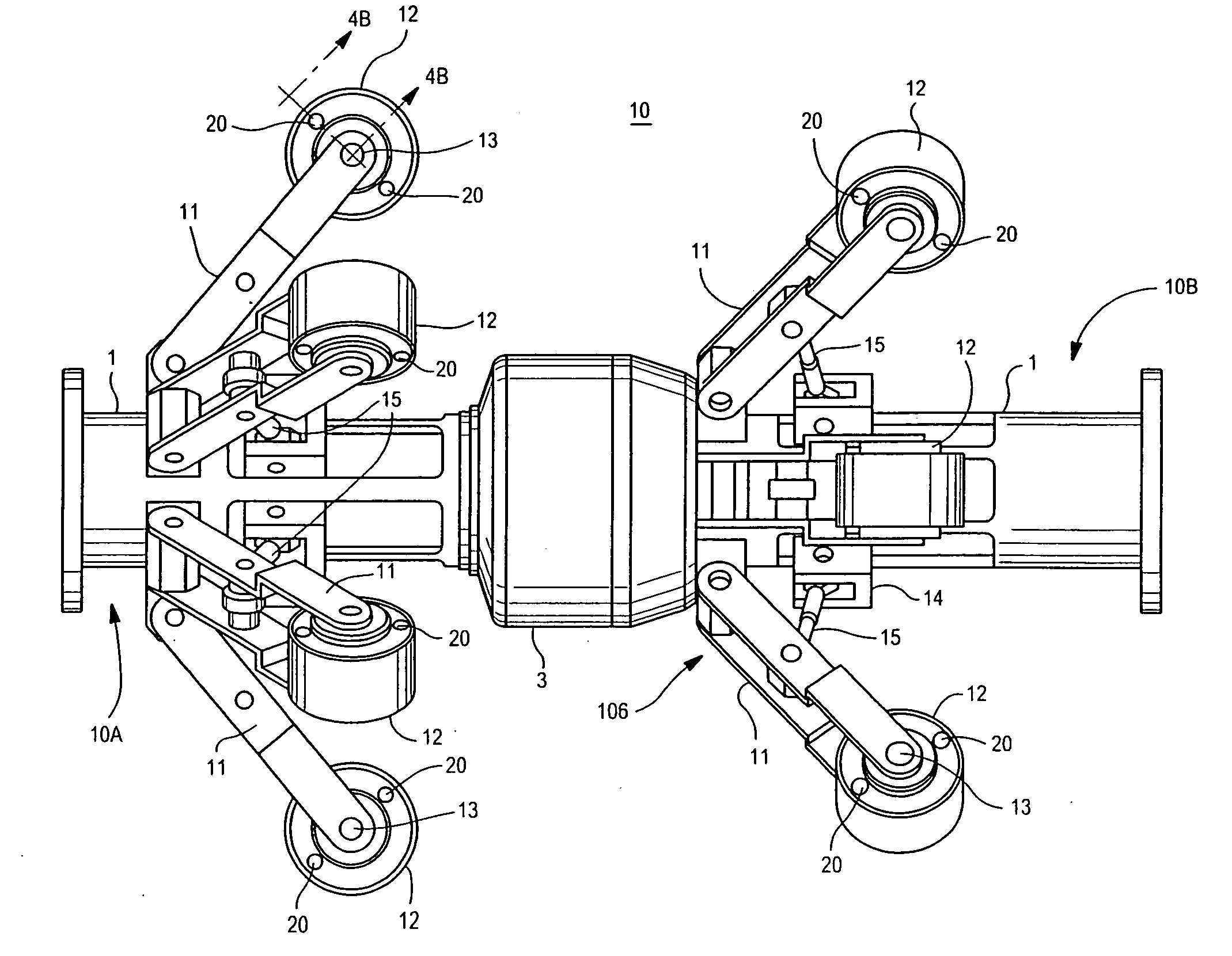
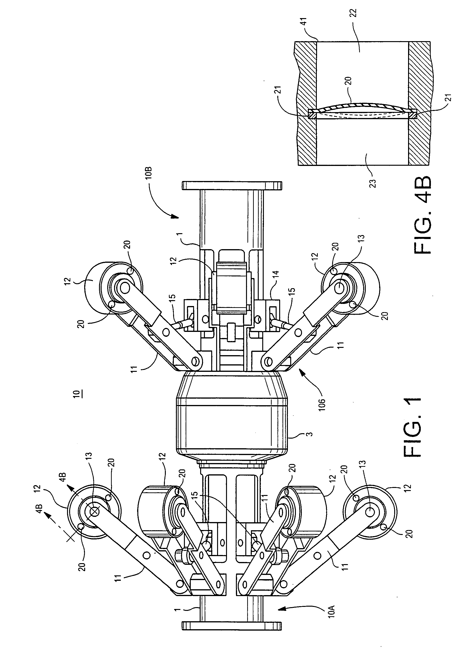
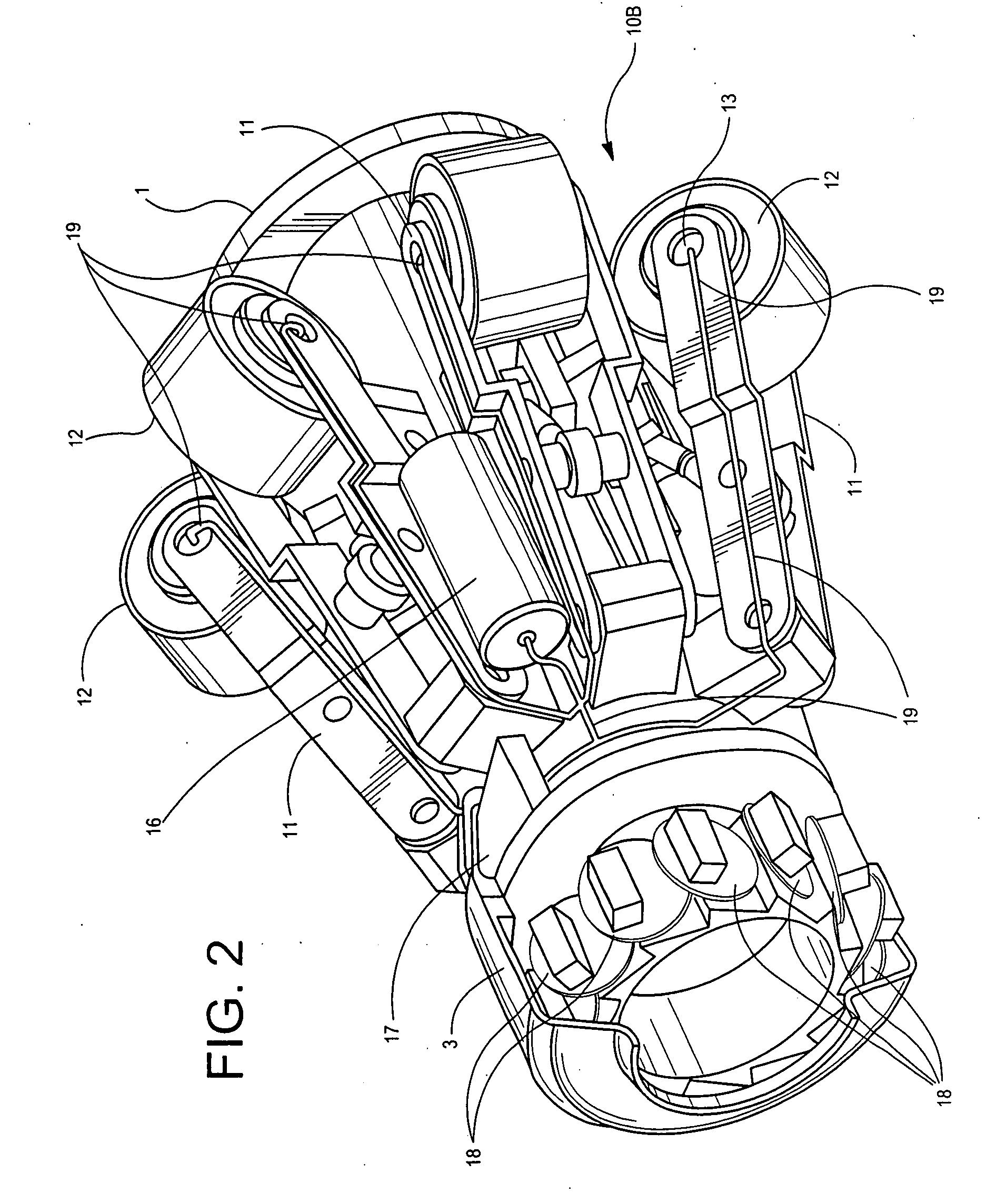
[0019]FIGS. 1 through 3 show various views of a non-limiting example implementation of a self-propelled mechanical crawler or tractor device 10 having self-contained motorized traction drive wheels 12 mounted on twelve drive wheel support extension arms that are pivotally attached and circumferentially arranged about the exterior of a basically cylindrically shaped main chassis 1. Alternative drive configurations having fewer or a greater number of circumferentially mounted drive wheel support extension arms with self-contained motor drive wheels are also possible for tractor 10.

[0020]FIG. 1 presents a side view of tractor device 10 in which only seven of the twelve drive wheel support extension arms with motorized drive wheel assemblies are visible. In this non-limiting illustrative example, tractor device 10 is made up of a modular front and rear chassis section (10a and 10b) with each chassis section having six radially arranged support extension arms 11 that each support a drive...


PUM


Abstract

A self-propelled crawler/tractor apparatus is disclosed for traveling through a tubular pipeline while conducting pipeline wall inspection operations and/or towing gear for cleaning, maintenance and the like. The crawler/tractor apparatus is propelled by a plurality of radially positioned motorized traction wheels. Each motorized traction wheel includes a brushless DC electric motor along with clutch, gearbox and other mechanical drive components integrated into a compact self-contained motorized wheel assembly which is sealed and filled with an electrically non-conductive lubricating/cooling oil. The seal integrity at each wheel assembly is maintained against oil leakage and debris ingress by a pressure-balancing mechanism which matches internal oil pressure to the exterior ambient pressure present in the pipeline. The electric motor drive for each traction wheel is individually controlled via an onboard computer to provide a wide range of torque and wheel speeds.

Description

BACKGROUND OF THE INVENTION[0001]This invention relates generally to a mechanical crawler or tractor device capable of traveling through a tubular pipeline and, more specifically, to a compact wheel drive assembly having an embedded electric motor for use in a pipeline tractor device.[0002]It is known in the art to cause inspection or cleaning pigs to be propelled through a pipe or tubing under the influence of a pressurized fluid. Conventionally, when inspecting the interior of a pipeline, the flow of the medium being transported is commonly used to drive forward the inspection system. However, if there is no fluid medium present or if there is only a low flow volume then the pipeline can not be traversed using such conventional driving means. In such cases, some sort of powered tractor device must be used to carry or pull the inspection apparatus through the pipeline. Although various types of self-powered tractor devices are known in the prior art, such conventional pipeline craw...

Claims


Application Information

Patent Timeline
Patent Type & Authority Applications(United States)
IPC IPC(8): B61B13/10
CPCF16L55/32
Inventor HERRON, WILLIAMWAGGOTT, ALAN A.
Owner GENERAL ELECTRIC CO
Why Eureka
Try Eureka