Method of performing electron diffraction pattern analysis upon a sample

Active Publication Date: 2016-12-08
OXFORD INSTR NANOTECH TOOLS
View PDF4 Cites 15 Cited by
  • Summary
  • Abstract
  • Description
  • Claims
  • Application Information

AI Technical Summary

Benefits of technology

[0029]In practice there may be encountered situations in which either no electron diffraction pattern, or a low quality electron diffraction pattern is achievable initially. In such cases it may be desirable to perform a further polishing or milling procedure using the particle beam. It is therefore advantageous if the rotation and, optionally translation, of the manipulator end effector is used to bring the specimen into th

Problems solved by technology

Obtaining of a diffraction pattern from a sample whilst mounted to an end effector presents particular challenges regarding the respective orientation needed together with the use of an

Method used


Image

  • Method of performing electron diffraction pattern analysis upon a sample
  • Method of performing electron diffraction pattern analysis upon a sample
  • Method of performing electron diffraction pattern analysis upon a sample

Examples


Example

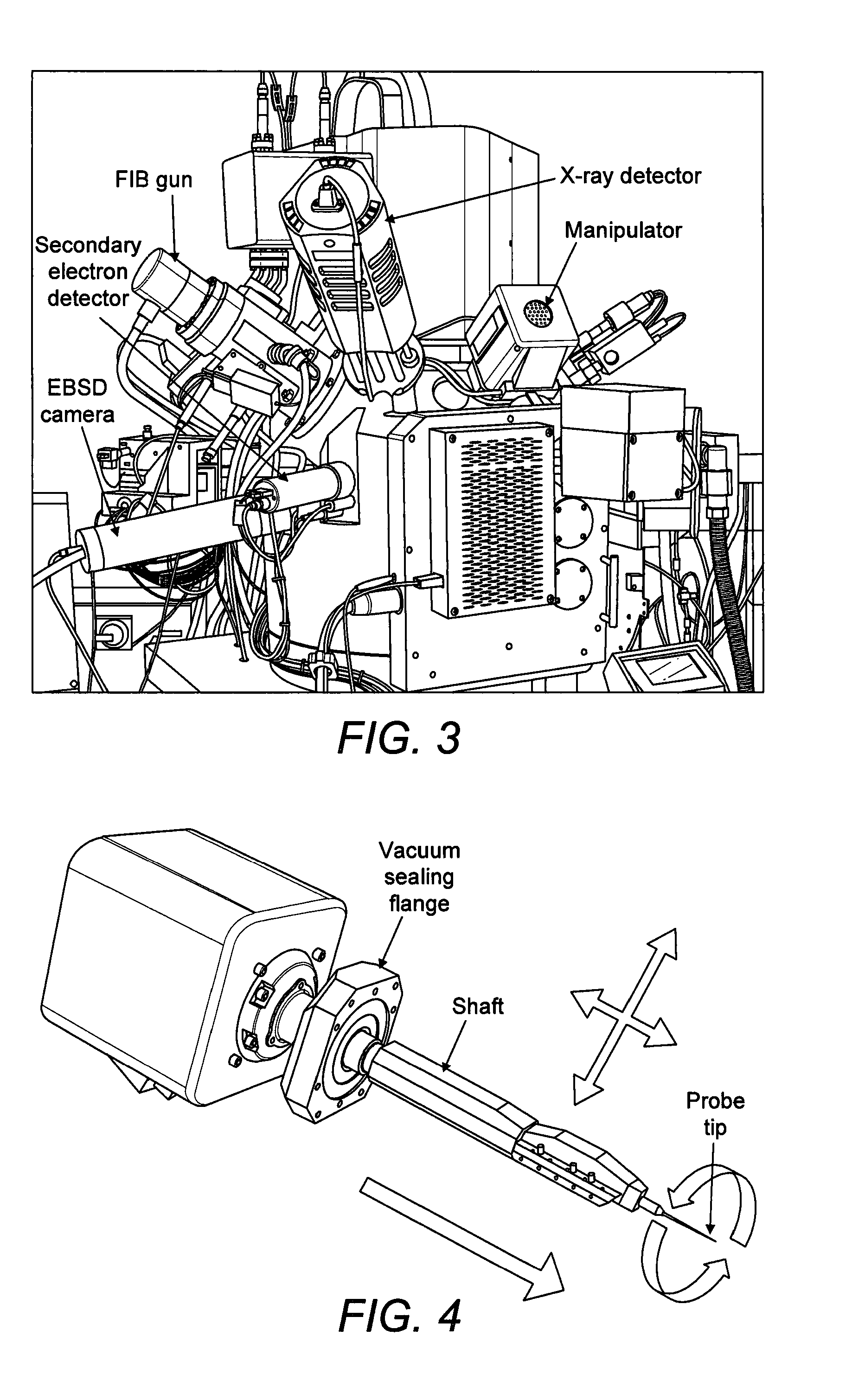
[0047]We now describe example methods effecting a procedure which, while in the vacuum chamber, extracts from the main specimen a small sample that contains the feature of interest and fixes it to the end of a probe that has a controllable rotation about an axis. The probe is arranged to be in a specific orientation with respect to a surface of the sample to be analysed. Thereafter electron diffraction analysis is performed on the sample held by the manipulator. Firstly we describe some practical points associated with the general method.

[0048]The initial procedure of isolation of the sample from the larger specimen is preferably achieved by milling using a focussed particle beam that could be a laser beam or a focussed ion beam (FIB). Using the “FIB lift-out” procedure, FIB milling may be used to isolate a small sample of material from the specimen, attach it to a manipulator end effector (probe) and lift it clear of the specimen. In particular, the FIB may be used to mill a trench...


PUM


Abstract

A method is provided for performing electron diffraction pattern analysis upon a sample in a vacuum chamber of a microscope. Firstly a sample is isolated from part of a specimen using a focused particle beam. A manipulator end effector is then attached to the sample so as to effect a predetermined orientation between the end effector and the sample. With the sample detached, the manipulator end effector is rotated about a rotation axis to bring the sample into a predetermined geometry with respect to an electron beam and diffraction pattern imaging apparatus so as to enable an electron diffraction pattern to be obtained from the sample while the sample is still fixed to the manipulator end effector. An electron beam is caused to impinge upon the sample attached to the manipulator end effector so as to obtain an electron diffraction pattern.

Description

FIELD OF THE INVENTION[0001]The present invention provides a method of performing electron diffraction pattern analysis upon a sample. The method is performed in situ within a vacuum chamber of apparatus such as a focussed ion beam scanning electron microscope.BACKGROUND TO THE INVENTION[0002]In a scanning electron microscope (SEM) a focussed electron beam is rastered over the surface of a specimen. At each point on the raster, an electron detector is used to record the varying signal due to electrons that have been scattered or emitted from the specimen and thus form an image of the rastered field of view. When a small object or feature, such as a particle or an inclusion, is present on the surface of a specimen and this feature is to be analysed, the focussed electron beam is directed on to the feature and X-rays are emitted. An X-ray spectrum can be collected with a suitable detector and used to identify the chemical elements present in the feature. Different types of electron de...

Claims


Application Information

Patent Timeline
IPC IPC(8): G01N23/20H01J37/295H01J37/20H01J37/252G01N23/203G01N23/205
CPCG01N23/20058G01N23/20025G01N23/203G01N23/2055H01J37/20H01J2237/20207H01J37/2955H01J2237/20214H01J2237/2544H01J2237/20221H01J37/252H01J37/3056H01J2237/24578H01J2237/31749
Inventor BAUER, FRANK WILLI
Owner OXFORD INSTR NANOTECH TOOLS
Why Eureka
Try Eureka