Connection support method for disk array device

a technology of disk array device and support method, which is applied in the direction of record information storage, electric apparatus casing/cabinet/drawer, instruments, etc., can solve the problems of complicated connection of cables in the disk array device, adverse effects, and the inability to attach tags to connector cables

Inactive Publication Date: 2005-06-23
HITACHI LTD
View PDF14 Cites 18 Cited by
  • Summary
  • Abstract
  • Description
  • Claims
  • Application Information

AI Technical Summary

Benefits of technology

[0011] The invention has been devised in order to solve such problems, and it is an object of the invention to provide a technique which can control misconnection of cables and cope with various connection methods in a disk array device.

Problems solved by technology

In such a method, costs for attaching tags to connector cables and coloring the connector cables are incurred.
Due to these tendencies, that is, the increase in the number of loops and the dual path, the connection of cables in the disk array device tends to be complicated and easily causes misconnection.
When misconnection occurs, the disk array device does not operate normally due to a cause such as inconsistency in a combination of disk devices constituting an FC-AL loop, which results in adverse effects such as deletion of stored data by mistake.
However, this method has a disadvantage in that the method can only cope with a standardized connection method considered in advance and a disadvantage in that, when a connection method is complicated, the color-coding includes a large number of colors, and excess costs and labor are required for preparation of cables and the like.

Method used

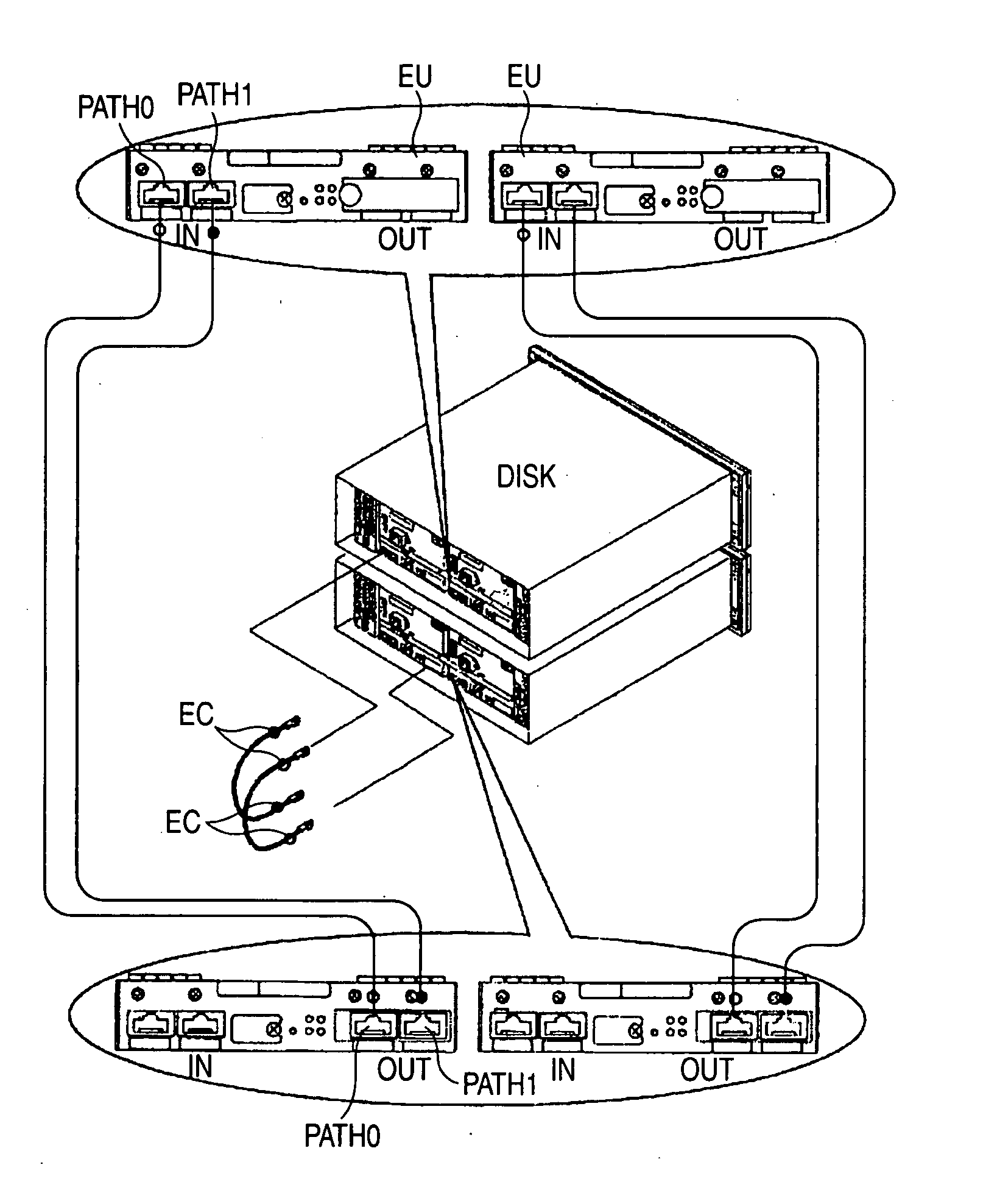
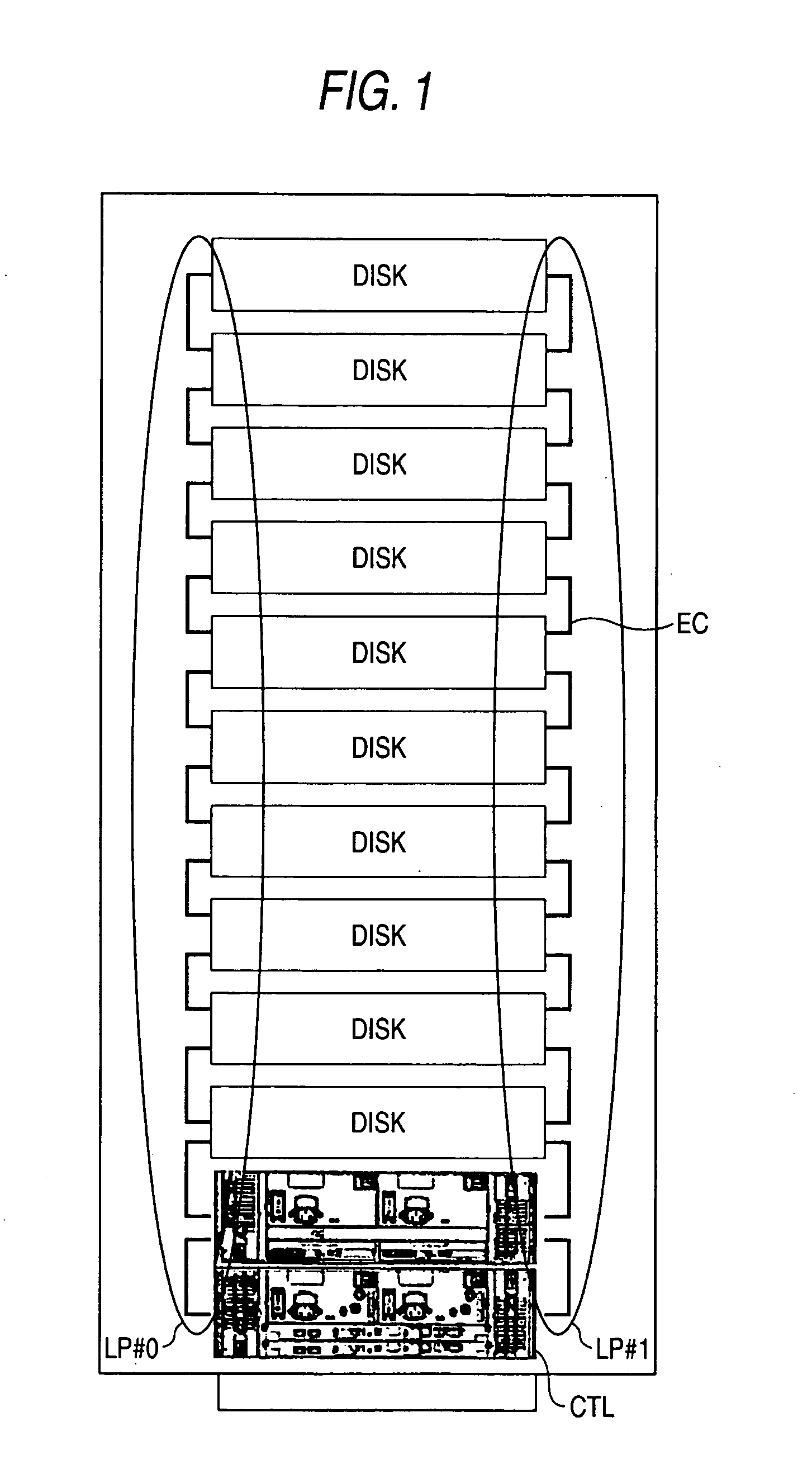
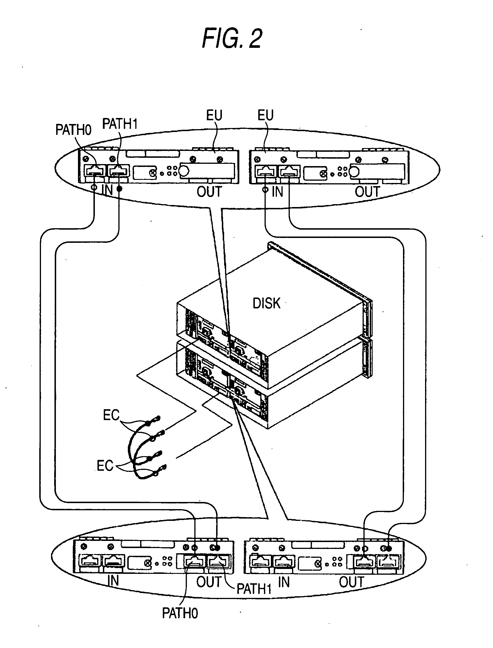

Image

  • Connection support method for disk array device
  • Connection support method for disk array device
  • Connection support method for disk array device

Examples


Embodiment Construction

[0040] Embodiments of the invention will be described in an order described below.

[0041] A. System structure

[0042] B. Connection navigating function

[0043] C. Modifications

A. System Structure

[0044]FIG. 3 is an explanatory diagram showing a schematic structure of an information processing system as an embodiment. In the information processing system, a storage device 1000 and host computers HC are connected by a SAN (Storage Area Network). The respective computers HC can access the storage device 1000 to realize various kinds of information processing. A management apparatus 10 is connected to a local area network LAN. A general-purpose personal computer having a network communication function or the like can be used as the management apparatus 10. A management tool 11, that is, an application program for setting an operation of the storage device 1000 and monitoring an operation state of the storage device 1000 is installed in the management apparatus 10.

[0045] In the storage ...


PUM

PropertyMeasurementUnit
colorsaaaaaaaaaa
failure resistance propertyaaaaaaaaaa
timeaaaaaaaaaa

Abstract

It is an object of the present invention to navigate connection among a controller housing and disk device housings which constitute a storage device. The controller housing, the disk device housings, and the like are stored in a storage device housing and are connected by ENC cables according to a typical connection method as preparation. A connection information file, which defines a connection state among respective connectors, is inputted to the controller housing. A controller lights or blinks LEDs of connectors, to which the ENC cables should be connected based on the connection information file, in a connection order. The controller navigates connection by sequentially lighting the LEDs of the connectors, which should be connected, in this way.

Description

CROSS-REFERENCES TO RELATED APPLICATIONS [0001] This application relates to and claims priority from Japanese Patent Application No. 2003-419087, filed on Dec. 17, 2003, the entire disclosure of which is incorporated herein by reference. BACKGROUND OF THE INVENTION [0002] 1. Field of the Invention [0003] The present invention relates to a support method of supporting cable connection between a controller housing (or unit), which is provided in a disk array device, and plural disk device housings (or units). [0004] 2. Description of the Related Art [0005] Plural disk devices are provided in a disk array device. A predetermined number of disk devices among these disk devices are stored in each of disk device housings. In disk array device housing, a controller housing, which contains a controller, and plural disk device housing are stored and connected by a fiber channel each other (see JP-A-9-330184). [0006] Input ports and output ports for connecting cables of the fiber channel are ...

Claims


Application Information

Patent Timeline
Patent Type & Authority Applications(United States)
IPC IPC(8): G06F1/18G06F3/06G11B33/12
CPCG06F3/0614G06F3/0653G11B33/126G06F3/0683G06F3/0658
Inventor SUZUKI, KATSUYOSHIHORI, MASANORI
Owner HITACHI LTD
Why Eureka
Try Eureka