Rainwater management system
A technology for managing system and rainwater, which is applied in the sewer system, waterway system, general water supply saving, etc. It can solve the problems of slowing water flow velocity, reducing water flow energy, affecting the drainage efficiency of siphon rainwater drainage system, etc., so as to improve drainage efficiency. , The effect of solving the diversion effect problem
- Summary
- Abstract
- Description
- Claims
- Application Information
AI Technical Summary
Problems solved by technology
Method used
Image
Examples
Embodiment 1
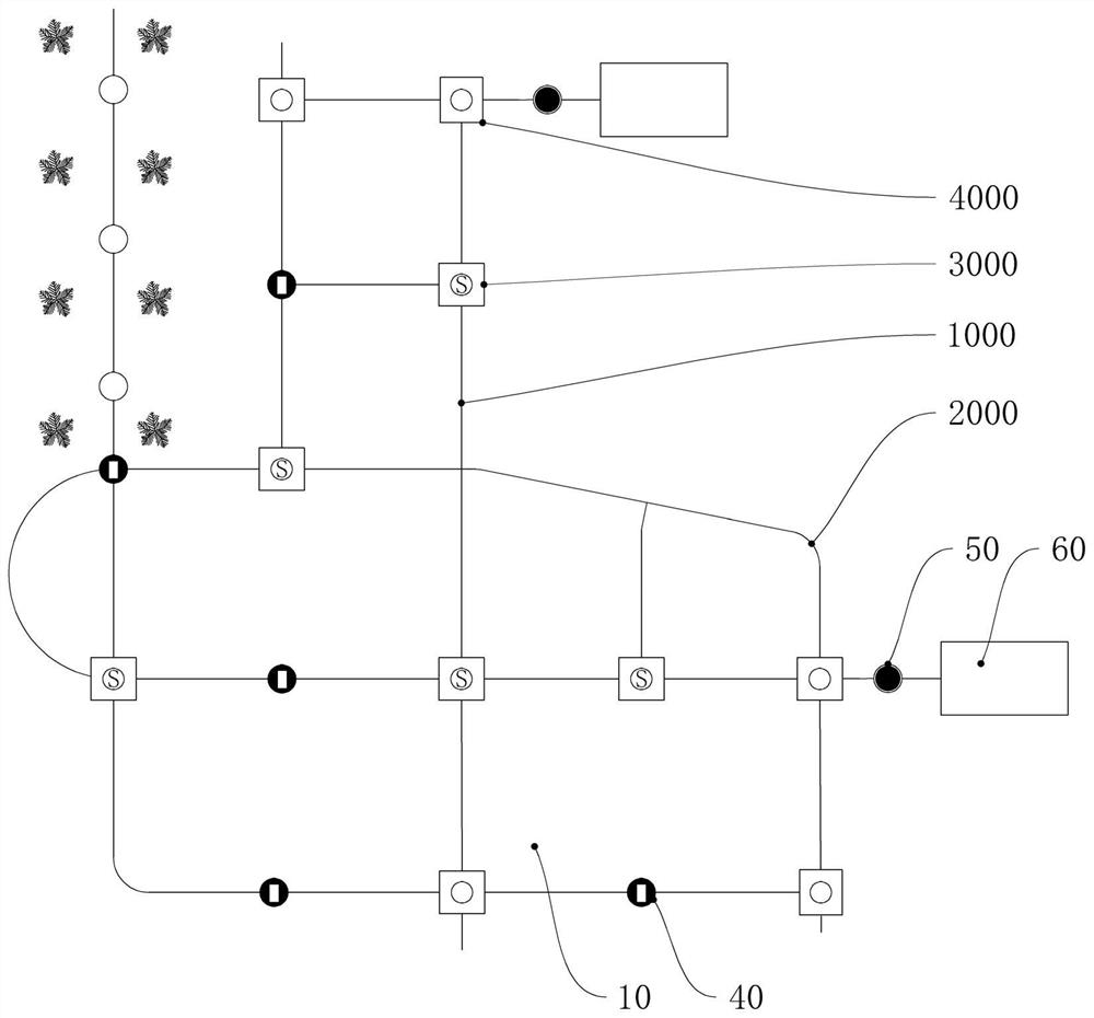
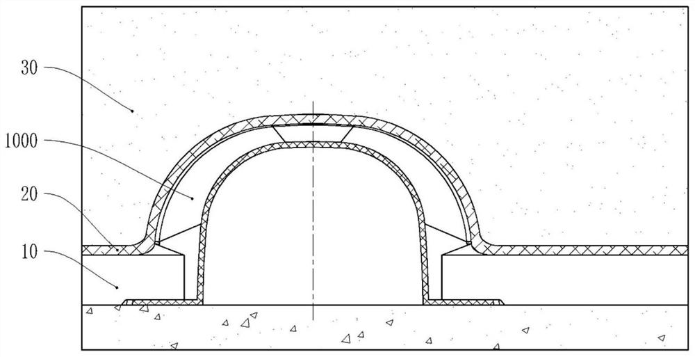
[0076] Such as figure 1 As shown, this embodiment is a rainwater management system, including a drainage board 10, a drainage network, and a water-permeable layer covering the drainage network. The drainage network includes at least a unit area: distributed around the unit area through drainage grooves Several siphon flow diverter devices 4000 connected to discharge water to the outside of the unit area; several variable flow drainage devices 3000 distributed on the nodes of the drainage network in the unit area, the variable flow drainage device 3000 is connected to one or more siphon deflectors 4000 through drainage grooves, and guides the water in different positions in the unit area to the suction deflectors; The water permeated by the permeable layer guides the water into the drainage tank.
[0077] The rainwater management system described in this patent is generally set under the filling layer and above the waterproof layer, including the drainage board 10, the drainag...
Embodiment 2
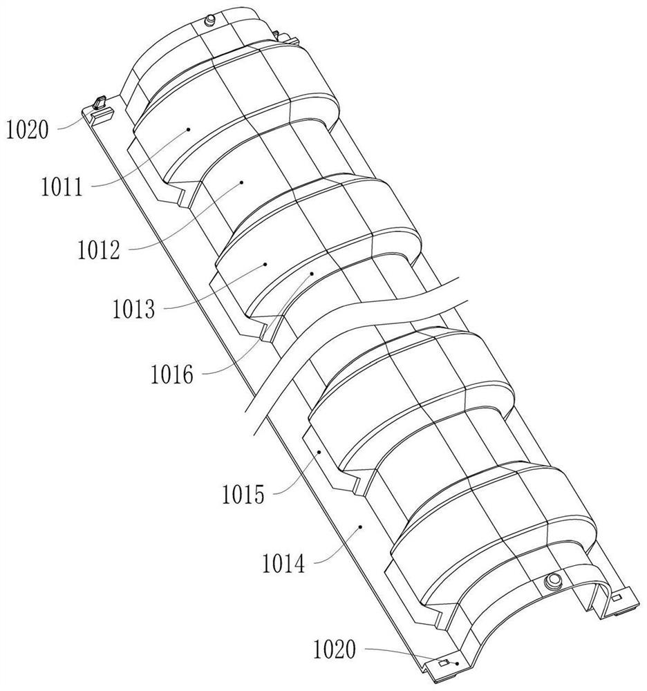
[0086] Such as Figure 2-2 , 2-3 , 2-4, this embodiment is a straight-through drainage tank 1000, including a tank body 1011, a bottom plate 1014, a water inlet 1015 and a buckle structure 1020, the opening of the tank body 1011 is downward, and the bottom plate 1014 is horizontally arranged on the tank body On both sides of the opening of 1011 , buckle structures 1020 are provided at both ends of the slot body 1011 in the longitudinal direction. The groove body 1011 is provided with protruding parts 1013 at intervals, and between two adjacent protruding parts 1013 is a non-protruding part 1012. It is an arched bulge connecting the bottom plates 1014 on both sides.
[0087] The protrusion 1013 has a certain length along the longitudinal direction of the tank body 1011 . The surfaces of the protruding portion 1013 and the non-protruding portion 1012 are smooth, and the entire tank body 1011 has no outward sharp ribs, which ensures that the geotextile is not cut. The protrud...
Embodiment 3
[0103] Such as Figure 3-1 , 3-2 As shown, the present embodiment is a kind of flexible drain tank 2000, including several drain tank units 2010, and the two ends of each drain tank unit 2010 are provided with connecting structures 2031; the drain tank units 2010 are connected to each other through the connecting structures 2031, and can rotate with each other; several drainage tank units 2010 are connected one by one in sequence to form the flexible drainage tank 2000 .
[0104] In this embodiment, the traditional straight-through drainage tank is divided into several drainage tank units 2010 through bionic design. Both ends of each drainage channel unit 2010 are provided with connection structures 2031 , and several drainage channel units 2010 are connected in sequence, and then assembled into a flexible drainage channel 2000 . Both ends of the flexible drainage groove 2000 can be connected with the above-mentioned straight drainage groove 1000 . On the one hand, since an...
PUM
 Abstract
Description
Claims
Application Information
 - R&D
- Intellectual Property
- Life Sciences
- Materials
- Tech Scout
- Unparalleled Data Quality
- Higher Quality Content
- 60% Fewer Hallucinations
Browse by: Latest US Patents, China's latest patents, Technical Efficacy Thesaurus, Application Domain, Technology Topic, Popular Technical Reports.
© 2025 PatSnap. All rights reserved.Legal|Privacy policy|Modern Slavery Act Transparency Statement|Sitemap|About US| Contact US: help@patsnap.com


