beverage canning equipment

A canning and beverage technology, which is applied in the field of beverage canning, can solve the problem of inability to realize the canning of bottles of different specifications, and achieve the effect of preventing beverage splashing and reducing hedging.

Active Publication Date: 2022-06-28
澳泰(广东)生物科技有限公司
View PDF6 Cites 0 Cited by
  • Summary
  • Abstract
  • Description
  • Claims
  • Application Information

AI Technical Summary

Problems solved by technology

[0002] With the improvement of living standards, the demand for beverages in the market continues to rise, and the resulting beverage canning technology has also been continuously improved. For example, the patent number is CN201720605159.5. , water treatment workshop, blending workshop, tank unloading workshop and canning workshop. The extraction workshop, water treatment workshop and blending workshop are used to dilute the original pulp to prepare beverages. The extraction workshop is composed of original pulp processing equipment. The processing workshop is composed of filtering equipment, which respectively send the raw pulp and water to the associated blending workshop, and the blending tank is connected to the canning machine through the conveying pipeline, and the tank unloading workshop includes an automatic tank emptying machine. The automatic emptying can machine is connected with a conveying channel, and the other end of the conveying channel is connected with the canning machine in the canning workshop, so as to realize the sealing of beverage cans on the canning machine, and the canning machine is also connected with the sterilizing kettle in the sterilizing workshop Combined, the high-temperature sterilization is completed in the sterilizer, but the disadvantage of this technical solution is that there is no way to realize the canning of bottles of different specifications

Method used


Image

  • beverage canning equipment
  • beverage canning equipment
  • beverage canning equipment

Examples


Embodiment

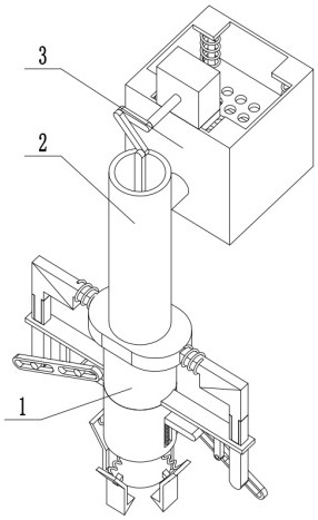
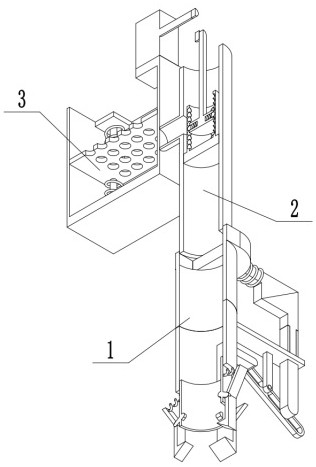
[0028] Combine below Figure 1-9 Illustrating this embodiment, a beverage canning device includes a canning component 1, a liquid pumping component 2, and a liquid tank component 3. The canning component 1 is connected to the liquid pumping component 2, and the liquid pumping component 2 is connected to the liquid tank component. 3-phase connection;

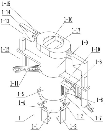
[0029] The canned assembly 1 includes a slidable sleeve 1-1, a clamping plate 1-2, a clamping plate push spring 1-3, a hinge column 1-4, a fixed sleeve 1-5, a driving sliding rod 1-6, a driving Sliding rod sliding column 1-7, driving sliding rod push spring 1-8, upper sleeve 1-9, outer end bracket 1-10, hinged rotating rod 1-11, driving sliding rod 1-12, driving sliding rod 2 1-13, drive slide bar three 1-14, drive slide bar push spring one 1-15, closing plate 1-16, connecting cavity 1-17, inner end card slot one 1-18, inner end card rod one 1- 19. The inner clamp rod push spring 1-20, the hinge column 1-4 is fixedly connected ...


PUM


Abstract

The invention relates to the field of beverage canning, in particular to a beverage canning equipment, which can realize the canning of bottles of different specifications, including a canning assembly, a liquid pumping assembly, and a liquid tank assembly, and drives a sliding rod through a hinged rotating rod One slides upward along the outer end bracket, and then drives the driving slider two to slide upward through the driving slider one, and then drives the driving slider three to move inward through the driving slider two, and then drives the driving slider three to move The closing plate moves inwardly at the same time, and then realizes the cut-off to the beverage that needs canning, finally realizes the automatic cutting off of the canning process, conveniently takes off the beverage bottle that has been canned. The driving sliding rod 2 can be relatively slid along the driving sliding rod 1, so that the distance between the driving sliding rod 2 and the driving sliding rod 1 changes, and then the driving sliding rod 2 drives the closing plate through the above-mentioned disclosed transmission relationship to realize The displacement of the interception changes, and finally realizes the canning of bottles of different specifications.

Description

technical field [0001] The invention relates to the field of beverage canning, in particular to a beverage canning device. Background technique [0002] With the improvement of living standards, the demand for beverages in the market continues to rise, and the resulting beverage canning technology is also constantly improving. For example, the patent number is CN201720605159.5. , water treatment workshop, mixing workshop, unloading workshop and canning workshop. The extraction workshop, water treatment workshop and mixing workshop are used to dilute the puree to prepare beverages. The extraction workshop is composed of puree treatment equipment. The treatment workshop is composed of filtering equipment. The two send the raw pulp and water to the associated blending workshop respectively. The blending tank is connected with the canning machine through the conveying pipeline. The unloading workshop includes an automatic can unloading machine. The automatic can unloading machi...

Claims


Application Information

Patent Timeline
Patent Type & Authority Patents(China)
IPC IPC(8): B67C3/24B67C3/26B67C3/22
CPCB67C3/24B67C3/26B67C3/22
Inventor 张满元
Owner 澳泰(广东)生物科技有限公司
Why Eureka
Try Eureka