Multifunctionally swivelling coupling assembly for fluid lines
a fluid line and multi-functional technology, applied in the direction of pipe supports, adjustable joints, pipe/joints/fittings, etc., can solve the problems of bending or other damaging forces, clustering of lines that sustain corresponding torsion, and prone to damage, so as to improve the safe range of motion of lines, and prevent external leakage of fluid
- Summary
- Abstract
- Description
- Claims
- Application Information
AI Technical Summary
Benefits of technology
Problems solved by technology
Method used
Image
Examples
first embodiment
The First Embodiment
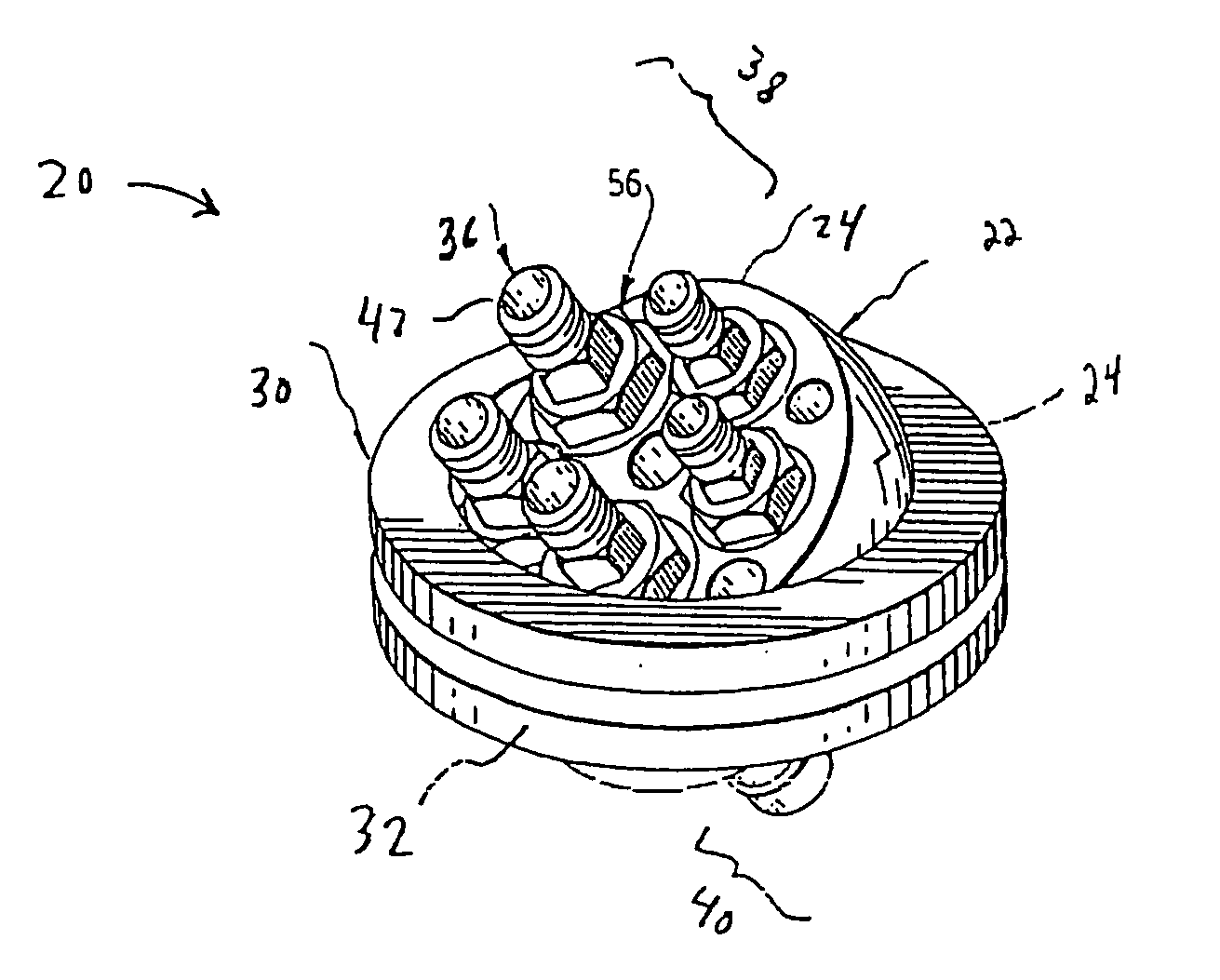
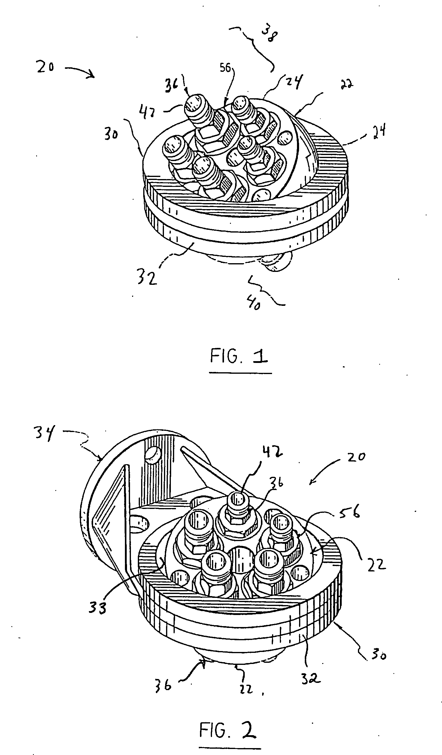
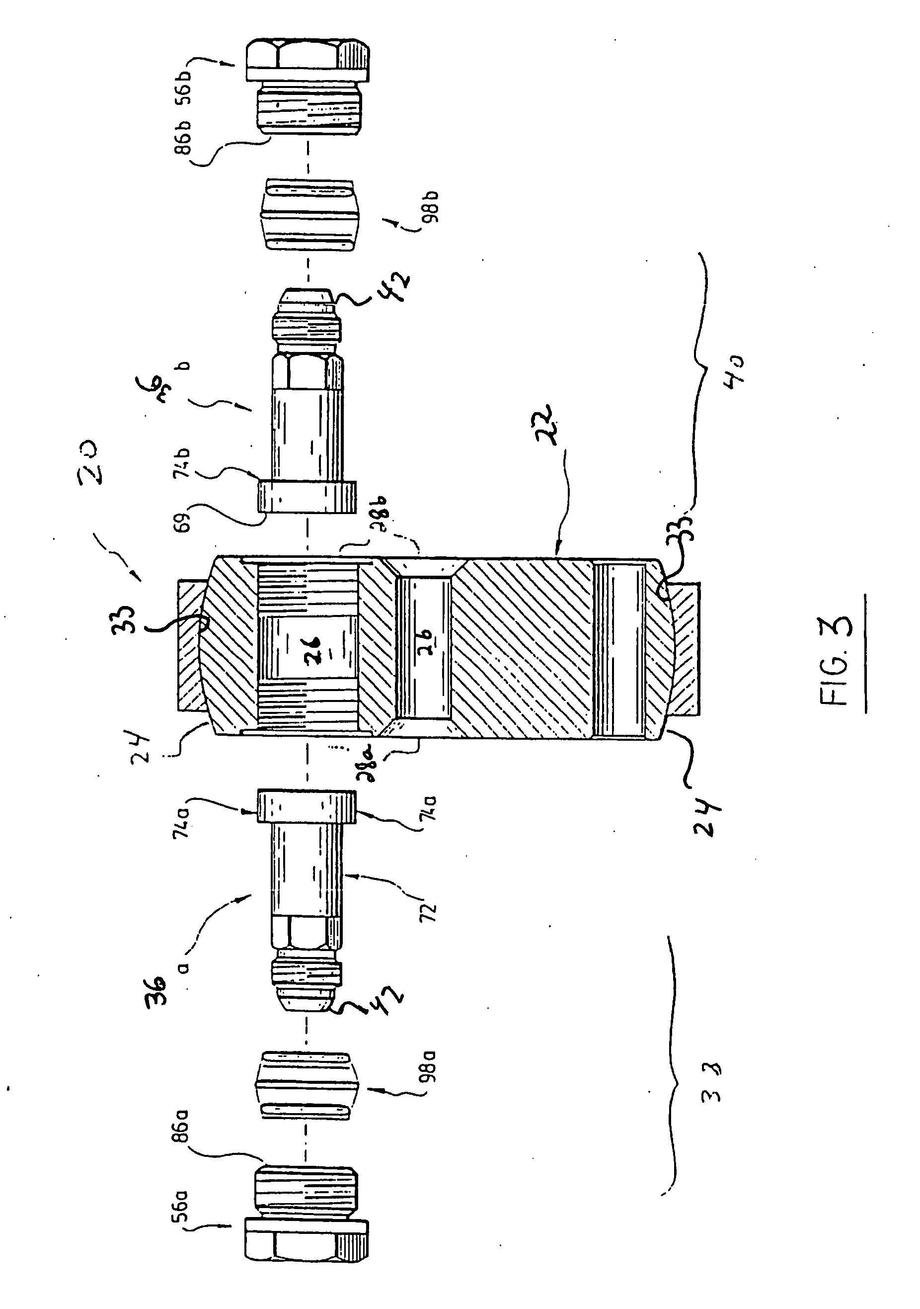
[0051] Referring the first embodiment shown in FIGS. 1-3, the assembly 20 includes a housing 22 having external surfaces 24. In this preferred embodiment, the housing 22 has a frustro-spherical shape and the external surfaces 24 are smooth and spherical.
[0052] The coupling assembly 20 provides an interconnection between pairs of lines. In the embodiment shown in FIGS. 1-3, five pairs of lines (not illustrated) may be connected through the assembly, but it will be understood that any appropriate number such as one or more of interconnections may be provided without departing from the scope of the present invention. Referring to FIG. 3, the housing 22 also has a bore 26 therethrough for each pair of lines (not illustrated). Each bore 26 has first 28a and second 28b apertures. Preferably, the bore 26 has a cylindrical and linear shape, but may alternatively have another configuration, such as angled or U shaped, for certain desired applications. It will be understo...
second embodiment
The Second Embodiment
[0063] Referring to the second embodiment shown in FIG. 4, and part of which is shown in FIG. 5, the assembly 20 again includes the male components 36 mounted within the housing 22 which in turn is mounted within the retention member 32.
[0064] As shown in FIG. 5, the housing 22 has external surfaces 24 defining a circular mating element 46 around the periphery of the housing 22, which preferably takes the form of a circular ridge, for mating with the retention member 30. The retention member 30 preferably comprises a groove (not shown) for mating and being in slide relation with the circular ridge. Of course, other mating elements, including an opposite ridge-groove configuration, may be used. In operation, the housing 22 rotates about an axis that is normal to the plane defined within the circular mating element.
[0065] Preferably, the axis about which the housing 22 rotates is the parallel with the axes of rotation of the male components 36.
third embodiment
The Third Embodiment
[0066] Referring to FIGS. 6-9 and 18-19, there may be a single male component 36 mounted within the housing 22, for interconnecting a pair of lines. Preferably, the male component 36 is swivellable within the housing 22. In the illustrations, the housing 22 has external surfaces 24 that are spherical to cooperate with a retention member (shown as 30 in FIG. 9) to provide the spherical swivelling of the housing 22 with respect to the retention member.
[0067] Referring to FIG. 9, in operation the two lines connected to the inlet 38 and outlet 40 sides may be swivelled independently, for instance in opposite directions if desired.
Preferred Mounting Arrangement of the Male Component
[0068] Referring now to FIGS. 6-8 and 10-19, a preferred mounting arrangement of the male component will be described. It should be noted that this construction is given by way of example and that the male component may be mounted within the bore of the housing in a variety of ways, dep...
PUM
 Abstract
Description
Claims
Application Information
 - R&D
- Intellectual Property
- Life Sciences
- Materials
- Tech Scout
- Unparalleled Data Quality
- Higher Quality Content
- 60% Fewer Hallucinations
Browse by: Latest US Patents, China's latest patents, Technical Efficacy Thesaurus, Application Domain, Technology Topic, Popular Technical Reports.
© 2025 PatSnap. All rights reserved.Legal|Privacy policy|Modern Slavery Act Transparency Statement|Sitemap|About US| Contact US: help@patsnap.com


