Compressor

A compressor and pressure setting technology, applied in the field of compressors, can solve problems such as abnormal temperature rise on the discharge side, and achieve the effect of improving operating efficiency

Active Publication Date: 2006-10-04
코벨코컴프레서가부시키가이샤
View PDF1 Cites 14 Cited by
  • Summary
  • Abstract
  • Description
  • Claims
  • Application Information

AI Technical Summary

Problems solved by technology

Furthermore, with the above-mentioned increase in the leakage amount, there is a problem that an abnormal rise in temperature also occurs on the discharge side.

Method used


Image

  • Compressor
  • Compressor
  • Compressor

Examples


Embodiment Construction

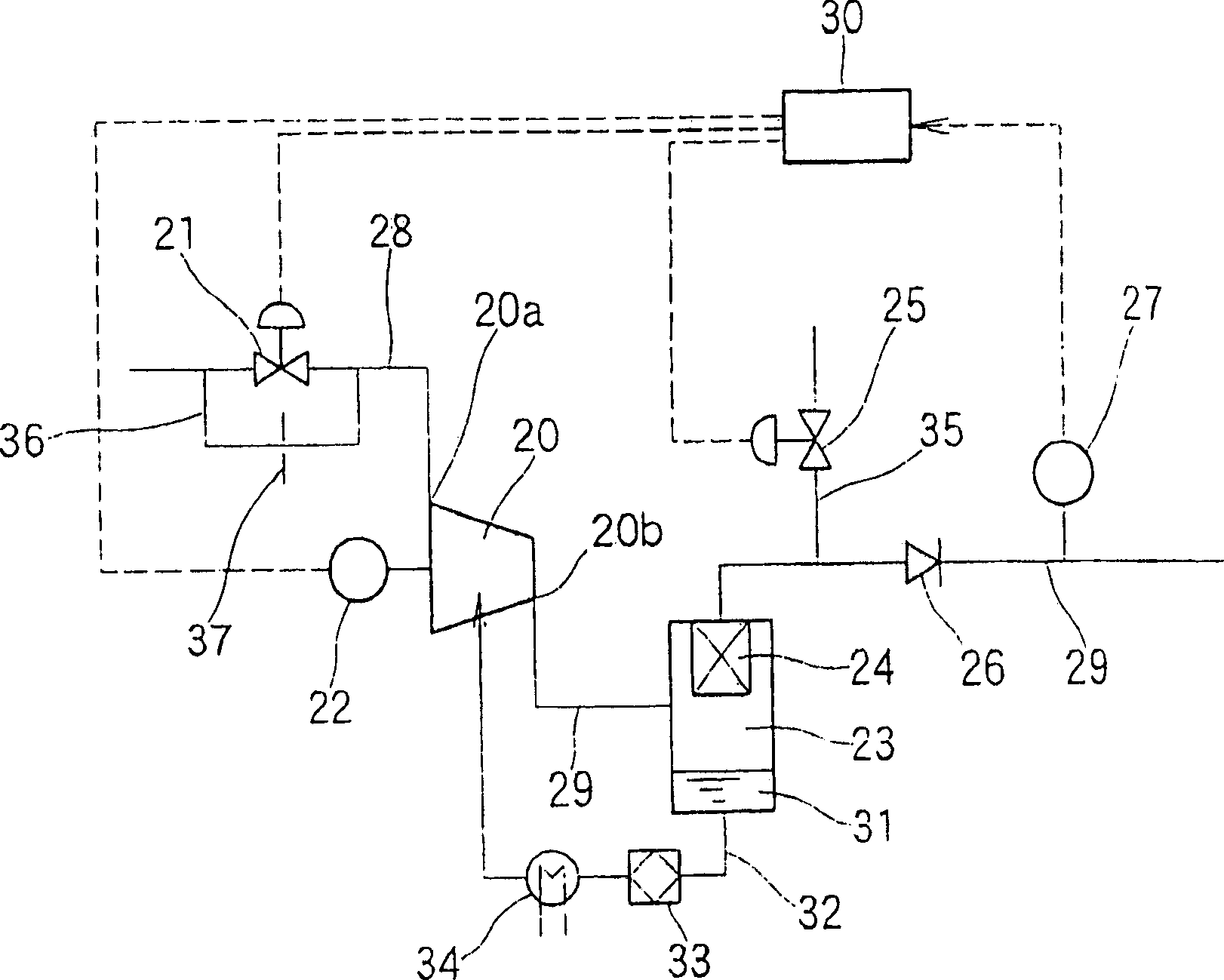
[0018] First refer to figure 1 The configuration of the compressor according to the embodiment of the present invention will be described. figure 1 It is a system diagram of the compressor according to the embodiment of the present invention, and more specifically, it is a system diagram when the present invention is applied to an oil-cooled compressor. Such an oil-cooled compressor (hereinafter referred to as a compressor) includes a compressor main body 20 having a structure in which a pair of male and female screw rotors (not shown) engage and are rotatably accommodated inside a rotor housing.

[0019] A suction flow path 28 is connected to the suction port 20a of the compressor main body 20, and a discharge flow path 29 is connected to the discharge port 20b. Also, one of the aforementioned pair of male and female screw rotors (usually a male rotor) constituting the compressor main body 20 is connected to a motor 22 .

[0020] By rotating the screw rotor with the motor...


PUM


Abstract

The invention relates to an oil-cooling compressor, which comprises a main body for compressing the gas of adsorption oil tube with adsorption adjusting valve to pass some gas when the valve is closed; a controller; a discharge valve on the discharge tube at the outlet of main body while the outlet is connected to the main body; a pressure detector for detecting the discharge pressure (P) at one side of gas feeding target near the one-way valve; the discharge pressure (P) is between up limit setting pressure (PH) and low limit setting pressure (PL); the controller can be based on discharge pressure (P) to set the switch state of adsorption adjusting valve and discharge valve, to process A operation control and B operation control. Therefore, it can avoid reducing compression efficiency relative to the load charge, and hold the discharge pressure at hope range.

Description

technical field [0001] The present invention relates to an improvement of a compressor, and more specifically, to a compressor capable of accurately responding to load fluctuations, and particularly to an operation control method thereof. Background technique [0002] In compressors equipped with a suction regulating valve on the suction side of the compressor body and a bleed valve on the discharge side, conventionally, when the pressure on the discharge side increases, the suction regulating valve is closed and the bleed valve is opened. Conversely, when the pressure on the discharge side is lowered, the discharge capacity is adjusted by the loading / unloading control operation in which the suction adjustment valve is opened and the discharge valve is closed. However, this method of operation has the disadvantage of poor operating efficiency because the produced compressed gas is released to the atmosphere through the purge valve during unloading. [0003] Therefore, the f...

Claims


Application Information

Patent Timeline
Patent Type & Authority Applications(China)
IPC IPC(8): F04B49/08F04B49/06F04C18/16F04C28/00
Inventor 中村元
Owner 코벨코컴프레서가부시키가이샤
Why Eureka
Try Eureka