Toner supply device

A technology for supplying devices and toners, which is applied in the fields of electro-recording, optics, instruments, etc., can solve the problems of large disconnection sound, high rigidity, and large bending force, and achieves reduced sound, low rigidity, and small bending force. Effect

Inactive Publication Date: 2006-10-04
KYOCERA DOCUMENT SOLUTIONS INC
View PDF1 Cites 10 Cited by
  • Summary
  • Abstract
  • Description
  • Claims
  • Application Information

AI Technical Summary

Problems solved by technology

[0004] However, when the free end of the agitating member breaks away from the upper end of the upright wall downstream of the toner storage portion as it rotates, and the agitating member is about to recover due to the bending force, the agitating member has high rigidity and a large bending force, so There is a problem that the disengagement sound produced is loud

Method used


Image

  • Toner supply device
  • Toner supply device
  • Toner supply device

Examples


Embodiment Construction

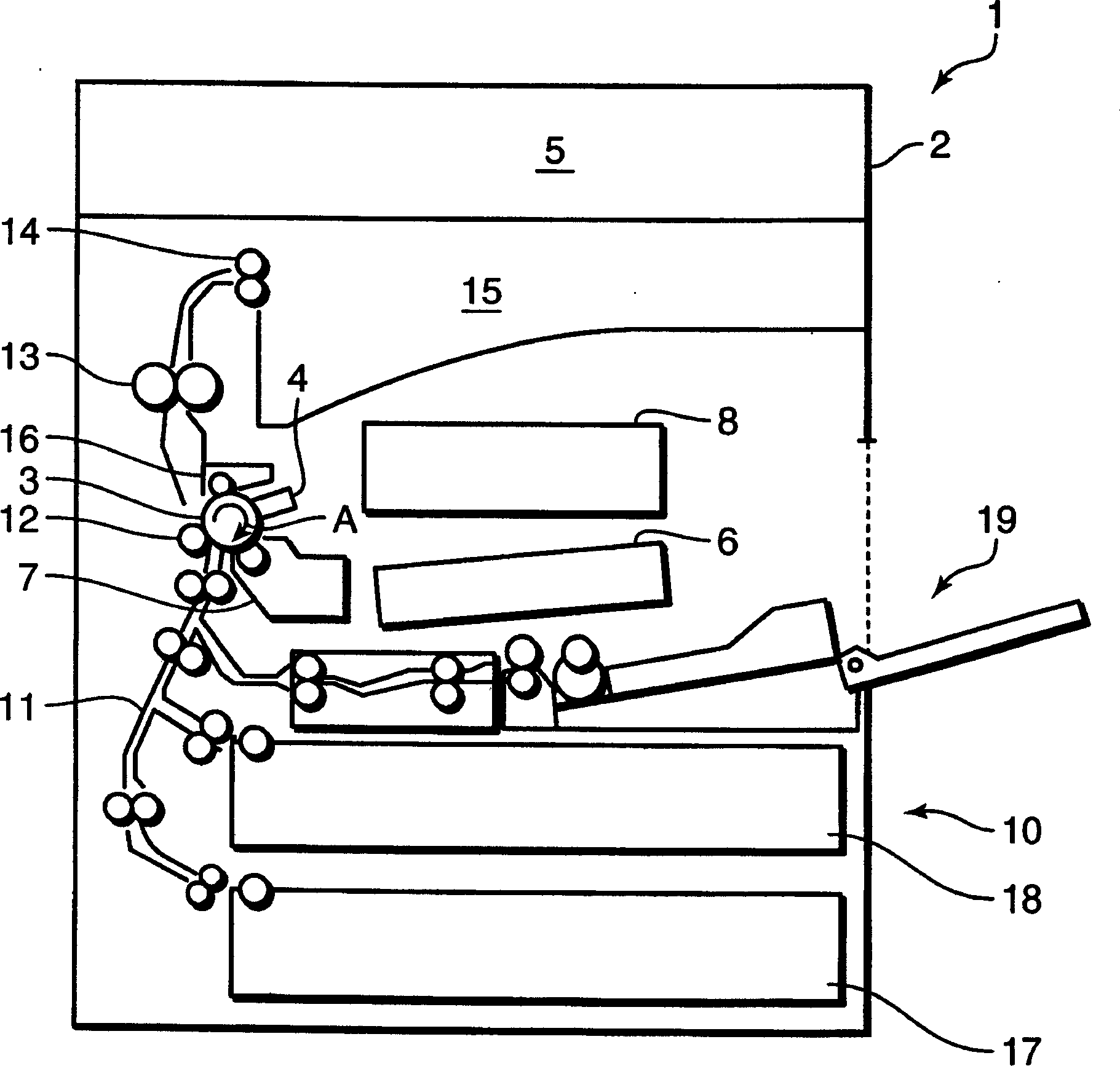
[0013] figure 1 It is a schematic diagram showing a schematic configuration of an electrophotographic copier 1 as an example of an image forming apparatus. In the copier main body 2 of the electrophotographic copier 1, the photosensitive drum 3 rotating in the direction A in the figure is charged by the charging unit 4, and the photosensitive drum 3 is charged according to the document image read by the document reading unit 5 from the laser scanning unit (LSU). ) 6 laser beam forms an electrostatic latent image on the surface of the photosensitive drum 3, and the developing unit 7 attaches toner to the electrostatic latent image to form a toner image. The supply of toner to the developing unit 7 is performed by the toner supply device 8 . Details of this toner supply device 8 will be described later.

[0014] The paper is transported from the paper feeding mechanism 10 to the photosensitive drum 3 on which the toner image is formed through the paper feeding path 11 , and th...


PUM


Abstract

Disclosed is a toner supply device including a toner container section ( 21 b), a rotating shaft ( 31 ) provided in the toner container section ( 21 b), and a stirring member ( 32 ) for stirring and feeding toner T to a supply opening ( 21 d) formed in the toner container section ( 21 b). The stirring member ( 32 ) includes an attachment portion ( 32 c) fixedly attached to the rotating shaft ( 31 ) and a free end portion ( 32 d) free to the rotating shaft ( 31 ). The free end portion ( 32 d) has a stiffness lower than the attachment portion ( 32 c). With this construction, a toner feeding rate can be maintained by the attachment portion ( 32 c) and sound occurring at a release of the free end portion ( 32 d) can be suppressed due to the free end portion ( 32 d).

Description

technical field [0001] The present invention relates to a toner supply device used in image forming devices such as electrophotographic copiers and laser printers. Background technique [0002] In the conventional image forming apparatus disclosed in Japanese Patent No. 3462860, a developing unit of the image forming apparatus has a toner supply device for supplying toner from a supply port. The toner is stirred by the rotation of the flexible stirring member installed on the rotating shaft in the toner storage part of the toner supply device, and the toner is moved along the vertical direction downstream of the toner storage part. The wall lifts upwards, carrying it to the downstream feed port. [0003] In the case of using a film-shaped plate made of a synthetic resin such as PET (polyethylene terephthalate) as the stirring member, if the thickness of the plate is increased (for example, the thickness is 0.125mm...high rigidity) , can enhance the transport capacity. [...

Claims


Application Information

Patent Timeline
Patent Type & Authority Applications(China)
IPC IPC(8): G03G15/08G03G15/00
CPCG03G2215/085G03G15/0822
Inventor 山村和由
Owner KYOCERA DOCUMENT SOLUTIONS INC
Why Eureka
Try Eureka