Method of soldering and solder compositions

A technology of solder and solder layer, applied in the direction of welding/cutting medium/material, welding equipment, welding medium, etc.

Inactive Publication Date: 2006-10-04
PPG IND OHIO INC
View PDF20 Cites 14 Cited by
  • Summary
  • Abstract
  • Description
  • Claims
  • Application Information

AI Technical Summary

Problems solved by technology

But the soldering method of the '988 patent still requires a separate soldering step to solder the leads to the busbar
In addition, the problem of local heating still exists when using high temperature molten solder

Method used


Image

  • Method of soldering and solder compositions
  • Method of soldering and solder compositions
  • Method of soldering and solder compositions

Examples


Embodiment 1

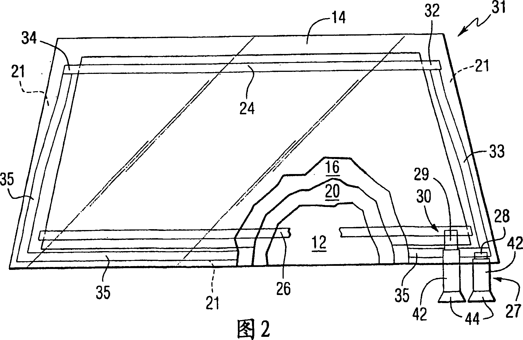
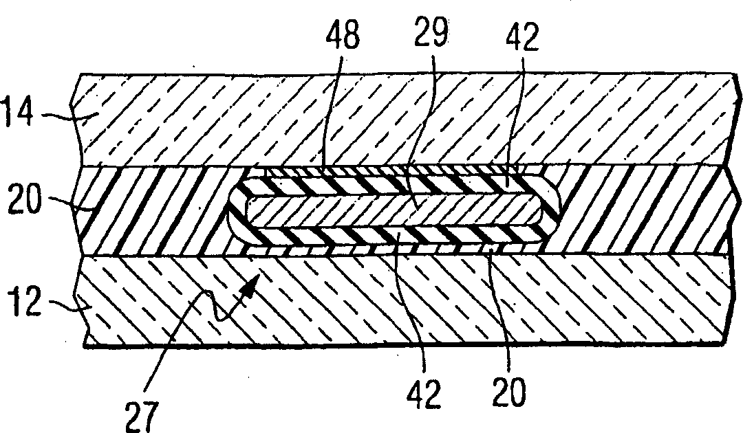
[0046] The invention will now be described with respect to the assembly of components for assembling a non-limiting embodiment of a windshield incorporating features of the invention. Flat pieces of glass shaped to provide glass blanks 12 and 14 are cut from the glass sheet and the edges of the cut pieces are stitched. A conductive ceramic paste is screen printed onto the inner surface of the flat glass piece of blank 14 to provide top busbars 24 and bottom busbars 26 . A black ceramic paste was screen printed onto the edge (not shown) of the inner surface of the glazing of the blank 12 (the intended No. The underlying adhesive provides UV protection. The flat glass piece with busbars and the flat glass piece with black ceramic strips were heated to a temperature of about 700° C. (371° C.) to secure the busbars and blank ceramic strips to their respective glass pieces. After the plate with the ceramic busbars has cooled, a continuous heatable coating of the type described ab...

Embodiment 2

[0050] A glass blank 12 is provided as described above in Example 1. The flat glass piece for the blank 14 is arranged as described above, except that the ceramic bus bars are not bonded to the glass piece. refer to Figure 6 , a circuit 64 such as an antenna circuit is applied on the No. 4 surface of the intended laminate, and a silver ceramic pad 66 is screen printed on the surface in electrical contact with the circuit 64 . The flat glass used for the blank 14 is heated to bond the gasket 66 to the glass. The conductive coating was applied to the inner surface of the glass for blank 14 (No. 3 surface of the desired laminate) as described above. The flat glass pieces for the blanks 12 and 14 are stacked on top of each other on a bent iron 70 of the type known in the art with the coated and black ceramic strips facing each other.

[0051] A bent iron on which the plates are supported moves through a tunnel furnace to heat the plates to their softening temperature. These s...

Embodiment 3

[0058] Glass blanks 12 and 14 were prepared as described in Example 2, except that a circuit 64 was provided on the surface of blank 14 and a ceramic liner 66 was not provided.

[0059] The composite board of Example 2 is placed on the profiled board 14 with the busbars in electrical contact with the coating 16 and the lead assemblies in contact with these busbars. Formed panels 12 were placed on composite 20 as described in Example 2, and the panels were laminated together as described below in the section entitled Laminating Cycle.


PUM


Abstract

The invention relates to using the heat generated during thermal treatment of one or more glass sheets to melt solder. In one nonlimiting embodiment, a lead providing external access to an electrical conductive arrangement, e.g. a conductive member between and connected to spaced bus bars between laminated sheets has an end portion of a connector, e.g. a lead soldered to each of the bus bars during thermal processing of the sheets, e.g. during the lamination of the sheets during a windshield manufacturing process. In another nonlimiting embodiment, the connector is soldered to the electrically conductive arrangement during the annealing of glass blanks following the heating and shaping of the glass blanks. Soldering the leads during the annealing or laminating process eliminated possible thermal damage to the sheet by having the sheet heated during the soldering operation instead of only a small surface portion of the sheet at and eliminates the cost of a separated soldering operation.

Description

technical field [0001] The present invention relates to a method of soldering, such as a method of making electrical connections, and solder compositions, and more particularly, to using heat absorbed by a member or part to melt solder to form a solder during a manufacturing process, such as during the manufacture of a laminated transparency. Points, such as soldering leads to bus bars of a heatable laminated windshield, and involve a low temperature melting solder composition. Background technique [0002] In the manufacture of laminated transparencies such as automotive windshields with conductive members such as heatable coatings and / or antennas between laminated glass sheets to transmit or receive signals, leads extend outward from between the laminated glass sheets to conduct electricity The member provides an external electrical pathway. US Patent No. 5,861,606 ("the '606 patent") describes a busbar system having a plurality of wires spaced apart and connected thereto...

Claims


Application Information

Patent Timeline
Patent Type & Authority Applications(China)
IPC IPC(8): B32B17/10B23K35/26H05B3/84B23K35/14
CPCB32B17/10376B23K35/02H05B2203/016B32B17/10036C03C17/36B32B17/10183B32B17/10761C03C2217/94C03C17/3673B23K35/26C03C27/046B32B17/10293B23K1/0016
Inventor J·A·温特C·E·贝利J·P·蒂尔C·S·弗尔特策尔
Owner PPG IND OHIO INC
Why Eureka
Try Eureka