
Selectively damping plantar insole

A technology for insoles and footwear, applied in the directions of insoles, footwear, soles, etc., can solve the problem of not having the combined function of improving vibration reduction and stability, etc.

Inactive Publication Date: 2006-10-11
让-吕克·朗泰
View PDF9 Cites 8 Cited by
  • Summary
  • Abstract
  • Description
  • Claims
  • Application Information

AI Technical Summary

Problems solved by technology

[0015] Until now, insoles have not had the combined function of improving the shock absorption and stability of the foot in the shoe

Method used


Image

  • Selectively damping plantar insole
  • Selectively damping plantar insole
  • Selectively damping plantar insole

Examples


Embodiment Construction

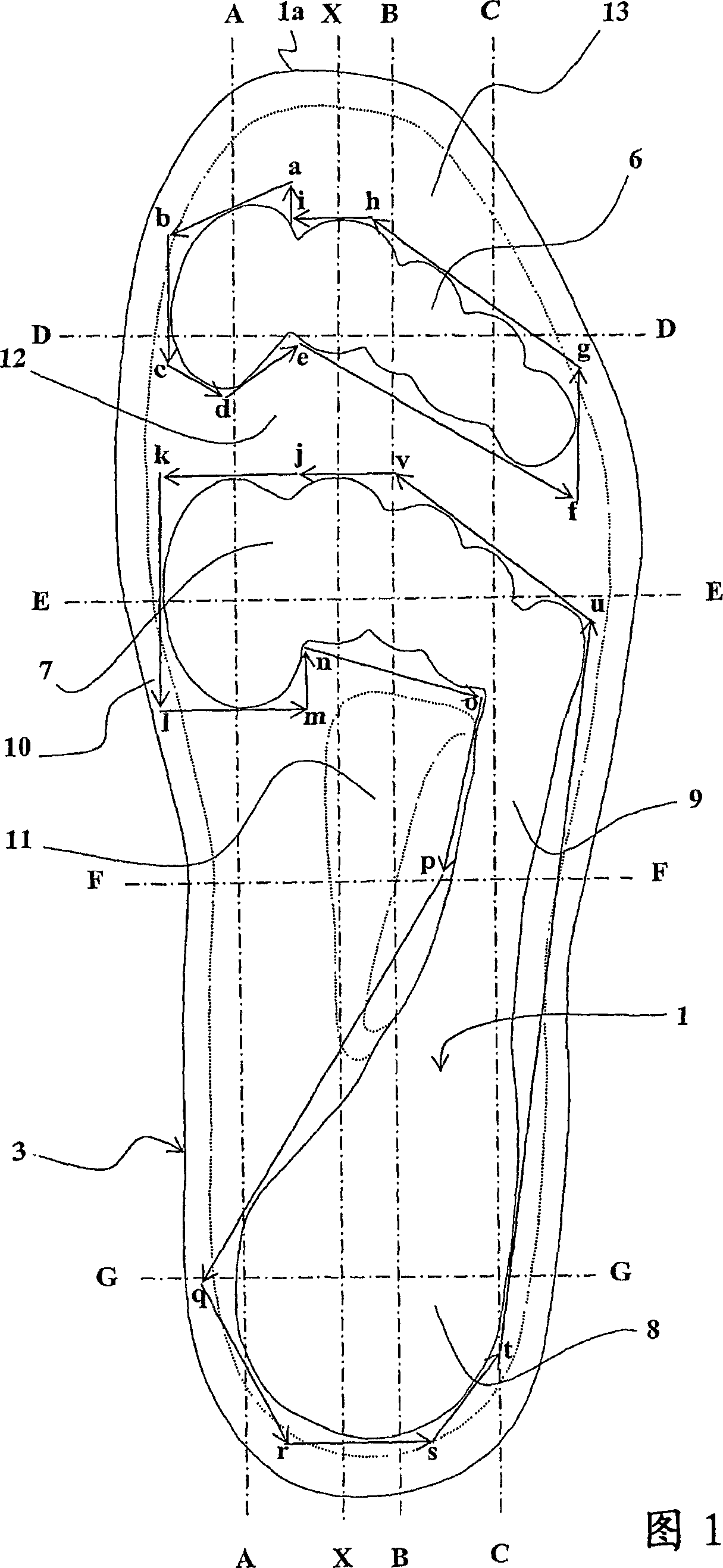
[0040] The embodiment of the insole of the invention shown in the figures is delimited by a main upper surface 1 , a main lower surface 2 and a peripheral contour 3 .

[0041] The main lower surface 2 is adapted to be in contact with a shoe sole. In the illustrated embodiment, the primary lower surface can fit into a shoe with the support surface of the shoe longitudinally contoured to emulate the common general anatomical curvature of the foot and laterally concave. The peripheral profile 3 is adapted to fit within the internal profile of the shoe and, for this purpose, has the usual curves of the peripheral profiles of insoles of the prior art, seen in plan view.

[0042] In the relaxed state, the upper main surface 1 has the general general shape of a shoe-liner, which shape may vary without departing from the scope of the invention.

[0043] Correspondingly, in Figures 2 to 4 In the embodiment shown in , the thickness of the insole varies slightly along a given longitud...


PUM


Abstract

The inventive plantar insole is characterised by bearing areas (6, 7, 8, 9) of the main surface which are provided with a rigidity or hardness which are less with respect to other areas (10-13) thereof. Said areas (6-9) are arranged under the major bearing areas of a foot, i.e. under toes, under the metatarsal heads, under the heel and under the external bearing area of the foot, thereby making it possible to attain a compromise between the necessity of an impact absorption and stabilisation of the foot in a shoe, and the insoles may be adapted to any type of footwear.

Description

technical field [0001] The present invention relates to insoles for use in footwear between the sole and the plantar surface of the user's foot. Background technique [0002] Prior art insoles are generally bounded by a main upper surface adapted to remain in contact with the plantar surface of the foot, a lower surface adapted to remain in contact with the sole, and a peripheral contour adapted to fit within the inner contour of the shoe. [0003] Insoles typically have objects for size or shape compensation to better fit the shoe to the user's foot. The thickness of the insole is chosen for this purpose and may vary with the area / area involved under the user's foot. [0004] Furthermore, footwear has been designed with integrated insoles having shock-absorbing properties in use. [0005] Thus, document US Pat. No. 4,364,189 A describes a shoe in which the insole comprises a foam material, one of the two halves of the foam material along the longitudinal axis of the foot ...

Claims


Application Information

Patent Timeline
Patent Type & Authority Applications(China)
IPC IPC(8): A43B17/14A43B13/12
CPCA43B7/141A43B13/12A43B7/144A43B7/145A43B7/143A43B1/0045A43B7/1445A43B7/1435A43B17/14A43B7/1425
Inventor 让-吕克·朗泰
Owner 让-吕克·朗泰
Learn More