Patient transfer cart capable of damping vibration when encountering obstacles
A cart and obstacle-encountering technology, applied in the field of patient transfer carts, can solve problems such as inability to reduce vibration, and achieve the effect of reducing friction and running resistance
- Summary
- Abstract
- Description
- Claims
- Application Information
AI Technical Summary
Problems solved by technology
Method used
Image
Examples
Embodiment 1
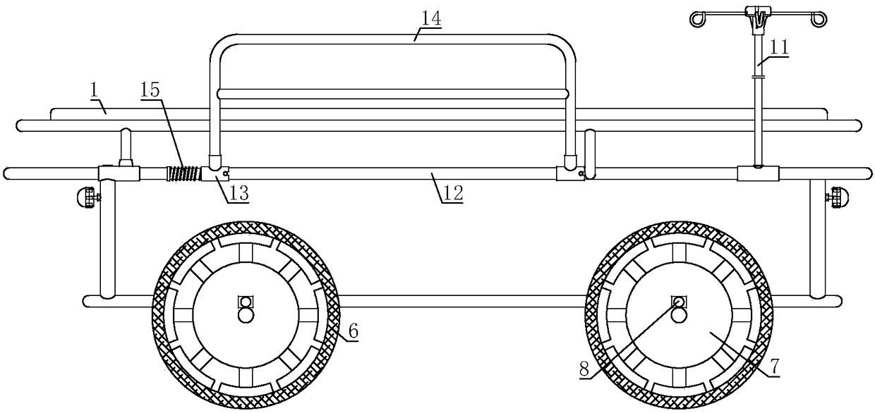
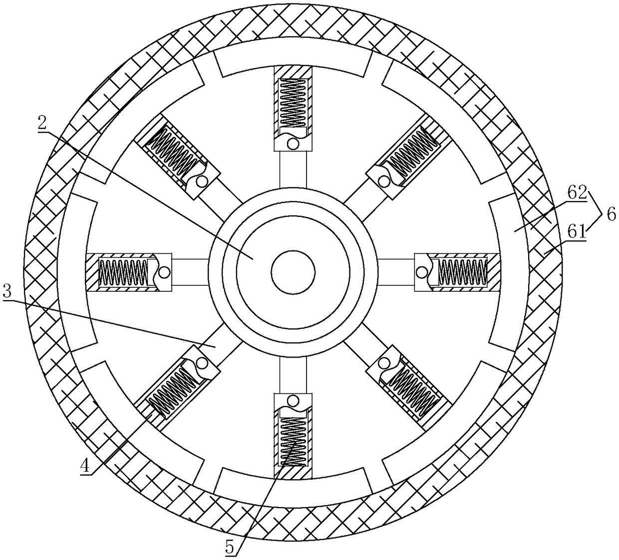
[0027] The patient transfer trolley for obstacle and vibration reduction includes a trolley main body 1 on which an infusion stand 11 is installed; the trolley main body 1 is connected with a wheel 2 through a bearing, and a number of supports are connected to the wheel 2. Rod 3, the other end of the rod 3 is provided with a sleeve 4, the rod 3 is sleeved in the sleeve 4, and a damping spring 5 is connected between the rod 3 and the sleeve 4; it also includes a damping wheel body 6 , the ends of several sleeves 4 away from the strut 3 are all connected to the damping wheel body 6 .
[0028] Several struts 3 are connected to the wheel disc 2 of the present invention. When the wheel encounters a bump on the ground, the part of the damping wheel body 6 that is in contact with the ground is squeezed and pushes the sleeve 4 there to move close to the struts 3. The damping spring 5 is compressed here. Due to the local deformation of the damping wheel body 6, the wheels are not thro...
Embodiment 2
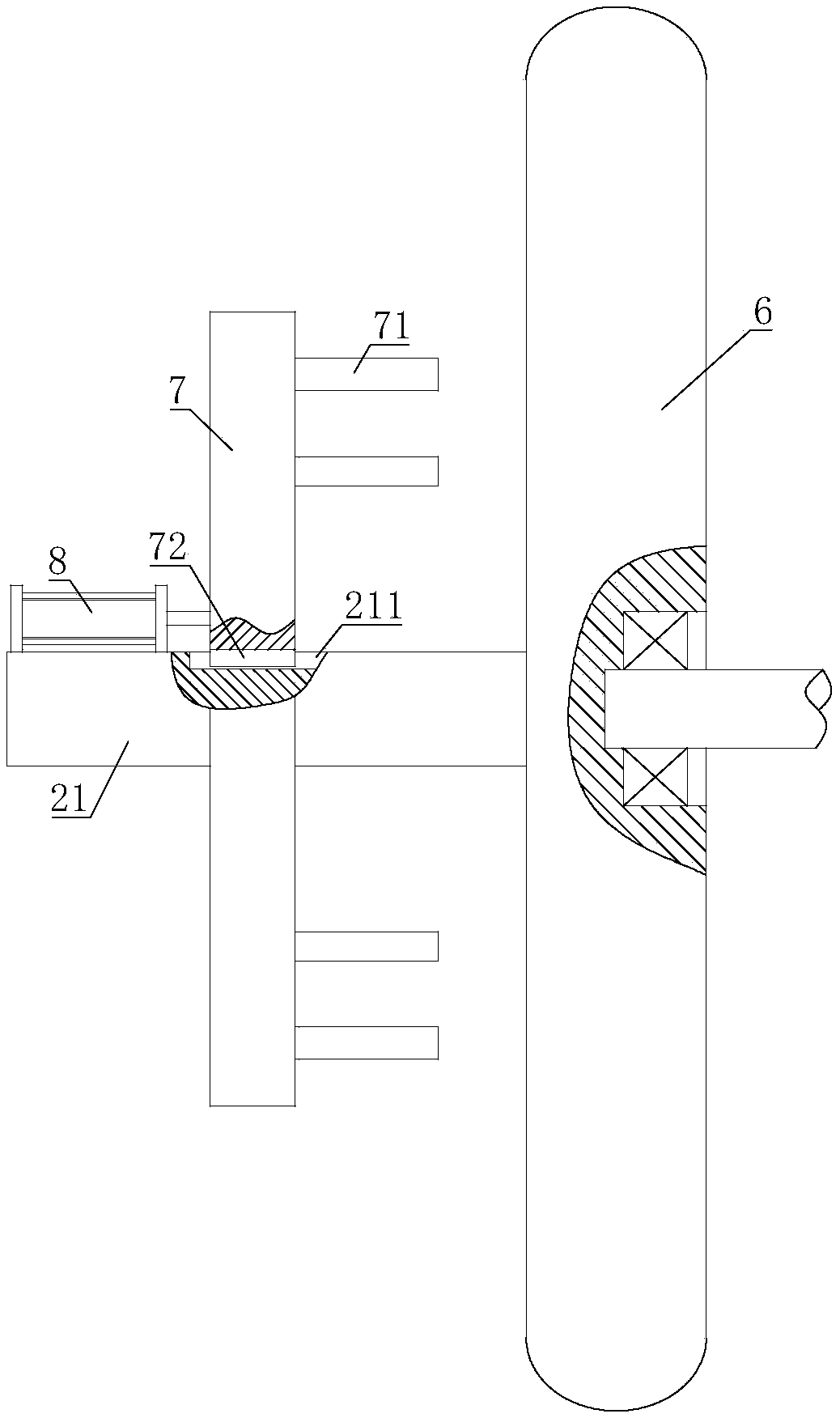
[0030] On the basis of Embodiment 1, through holes are provided on the support rod 3 and the sleeve 4, the connecting shaft 21 is fixed on the wheel disc 2, and the engaging disc 7 is sleeved on the connecting shaft 21, and the engaging disc 7 A plurality of connecting rods 71 for passing through the through holes on the sleeve 4 and the through holes on the pole 3 are connected thereto.
[0031] After the wheel of the cart main body 1 rolls over the raised ground, the engaging disc 7 can be pushed to the wheel disc 2, and the connecting rod 71 on the engaging disc 7 passes through the through hole on the pole 3 and the sleeve 4. At this time, the strut 3 cannot move relative to the sleeve 4, and the damping wheel body 6 cannot produce local deformation, so as to ensure the smooth rolling of the vibration damping wheel body 6 on the flat ground and reduce the friction between the vibration damping wheel body 6 and the ground .
Embodiment 3
[0033] On the basis of the first or second embodiment, the connecting shaft 21 is provided with a chute 211 , and the engaging disk 7 is provided with a slider 72 , and the slider 72 is sheathed in the chute 211 .
[0034] During the process of moving the engaging disc 7, the slider 72 always moves in the chute 211, avoiding the rotation of the engaging disc 7 relative to the wheel disc 2, and ensuring that the connecting rod 71 can be accurately inserted into the support rod 3 and the sleeve 4 In the through hole, ensure that the damping wheel body 6 can be locked in time.
PUM
 Abstract
Description
Claims
Application Information
 - R&D
- Intellectual Property
- Life Sciences
- Materials
- Tech Scout
- Unparalleled Data Quality
- Higher Quality Content
- 60% Fewer Hallucinations
Browse by: Latest US Patents, China's latest patents, Technical Efficacy Thesaurus, Application Domain, Technology Topic, Popular Technical Reports.
© 2025 PatSnap. All rights reserved.Legal|Privacy policy|Modern Slavery Act Transparency Statement|Sitemap|About US| Contact US: help@patsnap.com


