Spring damping mechanism with quick locking function

A vibration damping mechanism and functional technology, applied in the direction of spring/shock absorber, low internal friction spring, friction clamping detachable fasteners, etc., can solve the problem of random divergence and reliability affecting the optical axis and vibration damping direction and low service life, to avoid rigid connection, ensure stability, and delay impact time

Pending Publication Date: 2020-04-14
WUCHANG UNIV OF TECH +1
View PDF0 Cites 2 Cited by
  • Summary
  • Abstract
  • Description
  • Claims
  • Application Information

AI Technical Summary

Problems solved by technology

Because the photoelectric equipment of the sight is directly assembled on the top of the firearms and artillery, the multi-dimensional vibration impact will have a strong impact on the photoelectric equipment during shooting. In addition to seriously affecting the optical axis, it will also greatly reduce the life of core components such as the movement and detectors.
At present, the connection between photoelectric equipment and weapons usually adopts two connection forms: one is direct rigid connection, and the core components are all hard-resistant, and the reliability and life are very low; the other is the use of spring damping seat, because the spring can delay the impact time Therefore, the impact energy can still be effectively reduced, but the direction of its vibration reduction is random and uncontrollable, which cannot guarantee the precision of optoelectronic equipment
In addition, bolts are often used to connect the base to the weapon system, which is troublesome and time-consuming to disassemble and assemble.

Method used


Image

  • Spring damping mechanism with quick locking function
  • Spring damping mechanism with quick locking function
  • Spring damping mechanism with quick locking function

Examples


Embodiment Construction

[0030] The principles and features of the present invention are described below in conjunction with the accompanying drawings, and the examples given are only used to explain the present invention, and are not intended to limit the scope of the present invention.

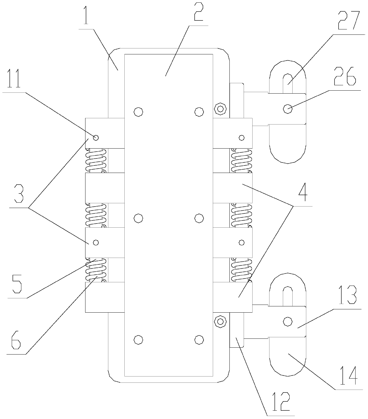
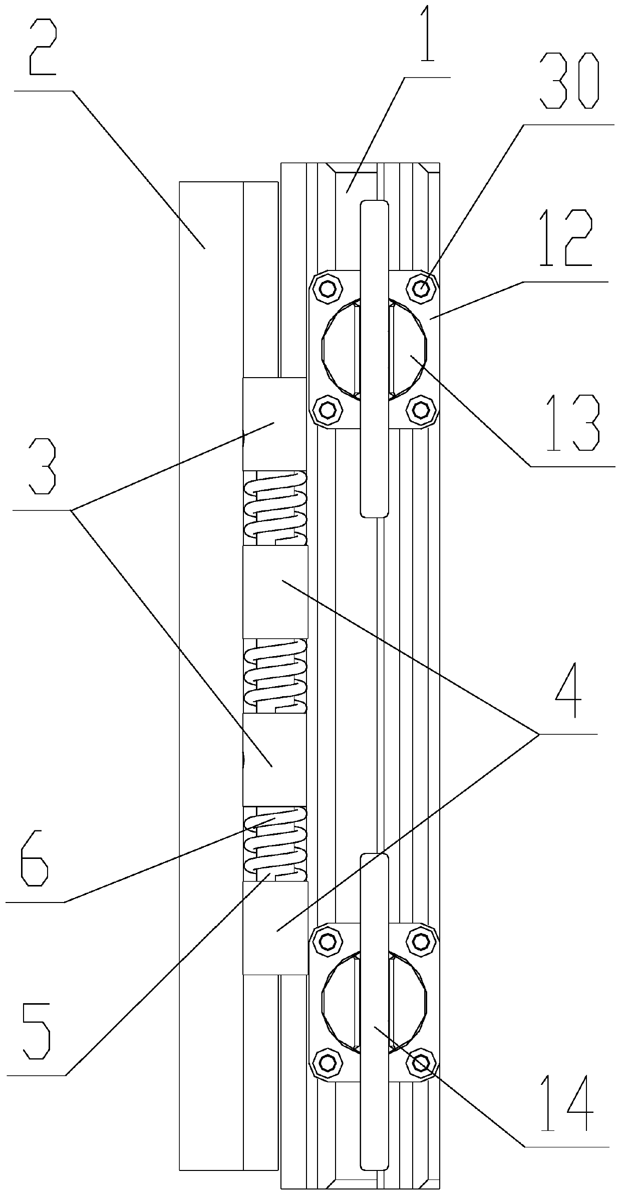
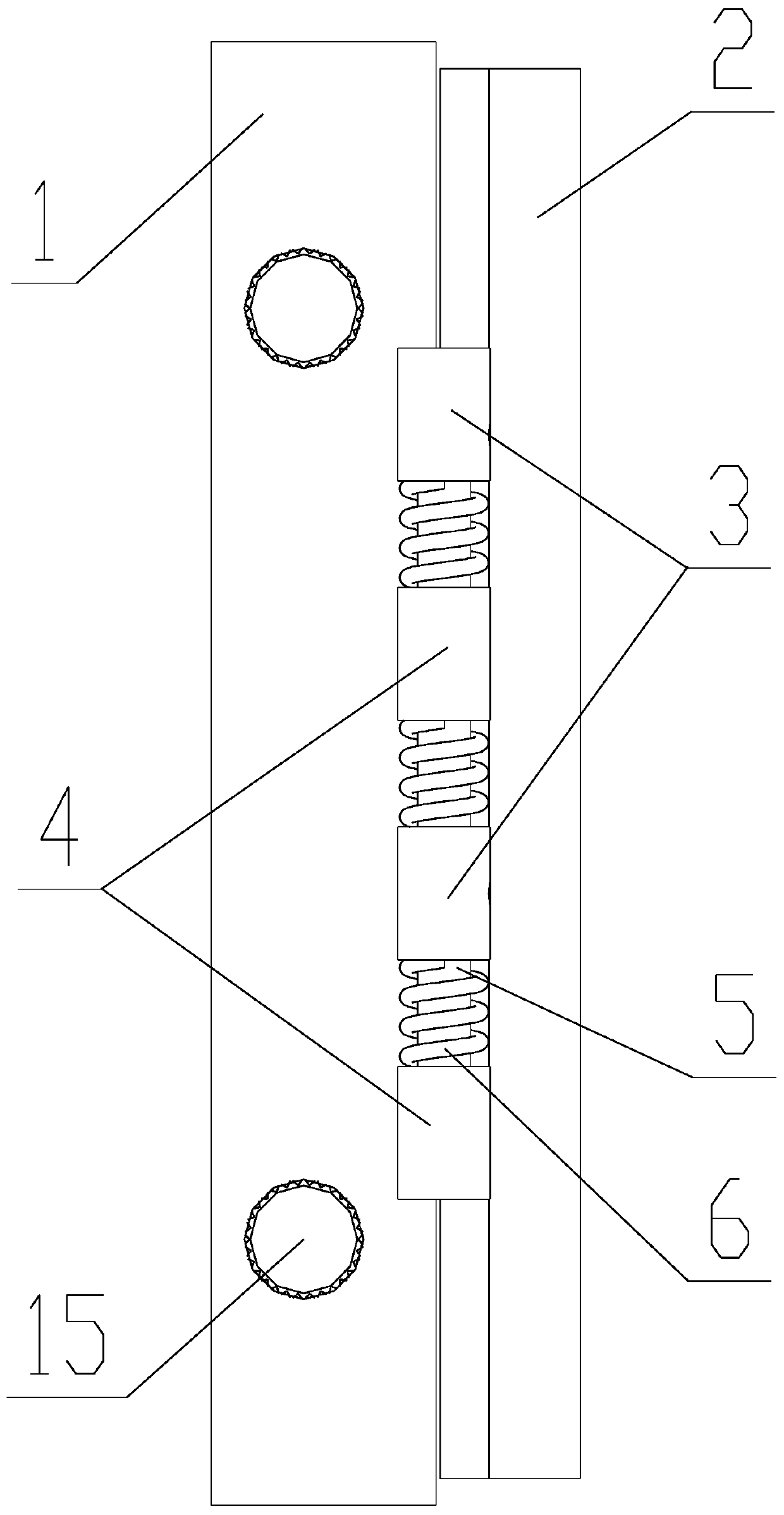
[0031] Such as Figure 1-7As shown, a spring damping mechanism with a fast locking function includes a base 1, a mounting base 2 and two guide rods 5, and two base guide rod supports 3 are fixedly connected to both sides of the base 1. Both sides of the mounting base 2 are fixedly connected with two mounting base guide rod bearings 4, the mounting base 2 is located on the top of the base 1, and one of the mounting base guide rod bearings 4 on each side Located between the two base guide rod supports 3 on the same side, each base guide rod support 3 is provided with a base guide rod support hole 9, each of the mount guide rod supports 4 There are mounting seat guide rod support holes 10 inside, the central axes of e...


PUM


Abstract

The invention relates to a spring damping mechanism with a quick locking function. The spring damping mechanism with the quick locking function comprises a base, an installation seat and two guide rods, wherein two base guide rod supports are fixedly connected to each of two sides of the base; two installation seat guide rod supports are fixedly connected to each of two sides of the installation seat; one installation seat guide rod support on each side is located between the two base guide rod supports located on the same side; a base guide rod support hole is formed in each base guide rod support; an installation seat guide rod support hole is formed in each installation seat guide rod support; each guide rod sequentially penetrates through the base guide rod support holes and the installation seat guide rod support holes in one same side; and a damping device is arranged between each base guide rod support and the corresponding installation seat guide rod support. The spring dampingmechanism with the quick locking function further comprises a locking device, wherein a quick clamping device is arranged on the bottom part of the base. The spring damping mechanism with the quick locking function has the beneficial effects that the guiding and damping problem can be solved at the same time, the stability of an equipment optical shaft and the reliability of the equipment under the severe environments such as strong vibration shock are guaranteed, and the base can be quickly locked on a weapon system.

Description

technical field [0001] The invention relates to a vibration damping mechanism, in particular to a spring damping mechanism with quick locking function. Background technique [0002] Due to its precision, opto-mechanical equipment has high requirements on the stability and consistency of the optical axis. Especially for aiming opto-mechanical equipment, it is even more necessary to ensure the optical axis. Because the photoelectric equipment of sights is directly assembled on the top of firearms and artillery, the multi-dimensional vibration and impact will have a strong impact on the photoelectric equipment during shooting. In addition to seriously affecting the optical axis, it will also greatly reduce the life of core components such as the movement and detectors. At present, the connection between photoelectric equipment and weapons usually adopts two connection forms: one is direct rigid connection, and the core components are all hard-resistant, and the reliability and ...

Claims


Application Information

Patent Timeline
Patent Type & Authority Applications(China)
IPC IPC(8): F16F15/067F16F3/04F16B2/06
CPCF16B2/065F16F3/04F16F15/067
Inventor 费国标
Owner WUCHANG UNIV OF TECH
Why Eureka
Try Eureka