Spotting Device and Method for High Concentration Spot Deposition on Microarrays and Other Micorscale Devices

a microarray and high-concentration technology, applied in the field of biotechnology, can solve the problems of severe concentration limitation of the method, the inability to flow a substance over a substrate to increase the spot deposition density, and the inability to achieve the same concentration limitation as the “pens”, so as to facilitate surface deposition, reduce the binding efficiency of a solute, and improve the effect of signal

Active Publication Date: 2007-10-04
UNIV OF UTAH RES FOUND
View PDF21 Cites 56 Cited by
  • Summary
  • Abstract
  • Description
  • Claims
  • Application Information

AI Technical Summary

Benefits of technology

[0017] In one embodiment, constant fluid flow of a solution containing a substance to be deposited is maintained for an extended period to facilitate surface deposition, forming a high-density spot. This embodiment allows the user to control for decrease binding efficiency of a solute to the surface, thereby forming an array having much higher signal (e.g., when using fluorescence, chemiluminescence, color-staining, other optically-based microarray sensing technologies, or radiometrics). In another embodiment, at least 10 microfluidic channels per cm2 are configured to produce a print head capable of producing individually addressed deposition sites (spots) on a surface. The 2-dimensional arrangement of the spots means that deposi

Problems solved by technology

In the '432 patent, one end of the capillaries may be attached to a reservoir; however there is no return path for the substance that is spotted and therefore no way to flow a substance over a substrate to increase the spot deposition density.
While prior art systems are capable of producing multiple spots of a controlled size, if the desired molecule for deposition is present in very low concentration, the total number of desired molecules that can be deposited on the surface is severely limited for a single spot.
The Perkin-Elmer BIOCHIP ARRAYER® uses “ink jet printing” technology, but that method has the same concentration limitation as the “pens.”
For an example of such a system see, U.S. P

Method used


Image

  • Spotting Device and Method for High Concentration Spot Deposition on Microarrays and Other Micorscale Devices
  • Spotting Device and Method for High Concentration Spot Deposition on Microarrays and Other Micorscale Devices
  • Spotting Device and Method for High Concentration Spot Deposition on Microarrays and Other Micorscale Devices

Examples


example ii

4.2 Example II

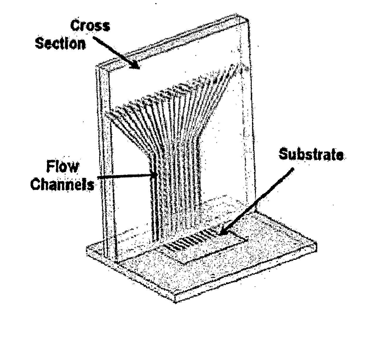
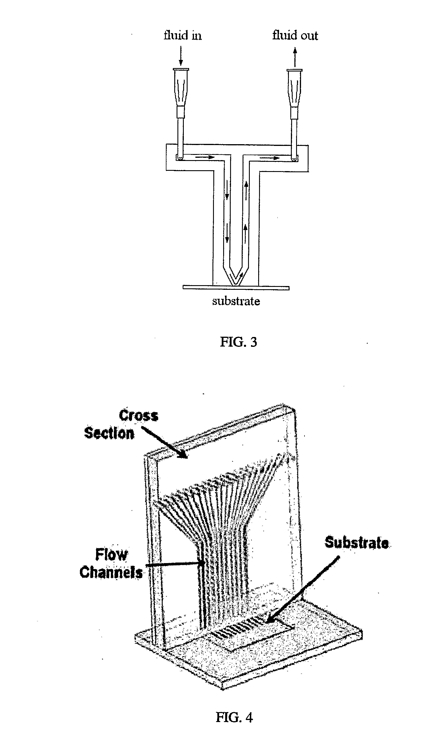
[0145] Spotter fabrication can be a three-stage process. First, PDMS, or any other suitable substance, is used to form a membrane on a mold (such as a lithographically-defined mold). Protrusions in the mold are used to define the spotting holes. This step creates the spotter face. Second, microchannels are formed on a second mold to connect to fluidic interconnects. Third, the microchannel layer is bonded to the backside of the spotter face. Both the spotter face and the microchannel layer are peeled simultaneously from the molds.

[0146] The membrane molding process yields a smooth lower surface, making spotter-substrate fluid sealing easier when the substrate is smooth. Fluid flow over each spot is individually controlled and spot shapes, number and arrangement can be customized as necessary. The mold may be adapted so that spotter face seals against uneven substrates, such as micro total analysis systems, biosensors, and transducers.

[0147] The spotter face and the s...


PUM

PropertyMeasurementUnit
Flow rateaaaaaaaaaa
Concentrationaaaaaaaaaa

Abstract

Disclosed is a spotter device and methods for the formation of microassays, biochips, biosensors, and cell cultures. The spotter may be used to deposit highly concentrated spots of protein or other materials on a microarray a slide, wafer, or other substrate. The spotter uses microfluidic conduits and orifices to deposit proteins, other biomolecules, or chemicals on a spot on a substrate. Each orifice is part of a fluid pathways that includes an inlet and outlet conduit. When the spotter contacts a substrate a seal is formed between the orifices and the substrate.

Description

PRIORITY CLAIM [0001] This application claims the benefit under 35 U.S.C. § 119(e) to U.S. Provisional Patent Application No. 60 / 585,697, filed on Jul. 6, 2004, the entirety of which is incorporated by reference.TECHNICAL FIELD [0002] The present invention relates generally to biotechnology, more specifically to building microassays, biochips, and biosensors. In particular, the present invention encompasses a system of microfluidic channels for the deposition of a substance on a substrate. BACKGROUND [0003] In recent years, a large number of biological / chemical analysis techniques have been demonstrated using micro-scale systems and have been implemented using micromachining technology. The rationale for using microscale technologies in analytical instrumentation includes reduction in instrument size and cost, reduction in sample and reagent volume, reduction in analysis time, increase in analysis throughput, and the possibility of integration of sample preparation and analysis func...

Claims


Application Information

Patent Timeline
IPC IPC(8): B05C5/00B05D1/36B05D5/00B23P17/00G01N1/28
CPCB01J19/0046Y10T29/49B01J2219/00367B01J2219/00369B01J2219/00371B01J2219/00497B01J2219/00527B01J2219/00536B01J2219/00574B01J2219/00576B01J2219/00585B01J2219/00596B01J2219/00605B01J2219/0061B01J2219/00612B01J2219/00619B01J2219/00621B01J2219/00626B01J2219/00628B01J2219/0063B01J2219/00637B01J2219/00639B01J2219/00644B01J2219/00648B01J2219/00659B01J2219/00675B01J2219/00677B01J2219/00691B01J2219/00693B01J2219/00722B01J2219/00725B01J2219/00731B01J2219/00734B01J2219/00736B01J2219/00743B01L3/0293B01L3/5027B01L3/502707B01L3/502715B01L3/50273B01L3/502761B01L2200/0647B01L2200/147B01L2300/0636B01L2300/0654B01L2300/0822B01L2300/0877B01L2300/1827B01L2400/0415B01L2400/0487B82Y30/00C40B50/14C40B60/14G01N35/1002G01N35/1065G01N35/1074G01N2035/00158G01N2035/1034G01N2035/1039C12M23/16B01J2219/00353B01L3/00B01L3/02G01D15/00
Inventor GALE, BRUCECHANG-YEN, DAVIDMYSZKA, DAVID
Owner UNIV OF UTAH RES FOUND
Why Eureka
Try Eureka