
Method for cell scheduling in a communication network

A scheduling table, transmission unit technology, used in data exchange networks, electrical components, digital transmission systems, etc.

Inactive Publication Date: 2006-10-11
KONINKLIJKE PHILIPS ELECTRONICS NV
View PDF1 Cites 3 Cited by
  • Summary
  • Abstract
  • Description
  • Claims
  • Application Information

AI Technical Summary

Problems solved by technology

This allows additional bandwidth for the server to potentially have an opportunity to service its queue

Method used


Image

  • Method for cell scheduling in a communication network
  • Method for cell scheduling in a communication network
  • Method for cell scheduling in a communication network

Examples


Embodiment Construction

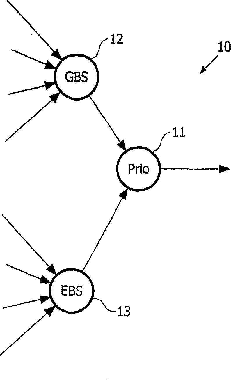
[0033] figure 1 Nodes representing schedulers 10 known in the prior art, they may be based eg on strict priority servers 11 as shown here. Strict priority server 11 is served by guaranteed bandwidth server 12 and additional bandwidth server 13 .

[0034] The network elements of the current packet-switching network usually divide the variable-length packets arriving at the node into fixed-length units, so that the transmission of the units can be managed uniformly within the node. Fixed-length cells enable memory management of the data buffers storing these cells. In order to provide a particular quality of service, the ability to transmit some units more quickly than others is required, which is only possible by delaying some units. To provide different latencies to different streams of units waiting to be serviced by the scheduler, the units can be placed in multiple queues.

[0035] In conventional systems, scheduling unit transfers typically involves inserting queue poin...


PUM


Abstract

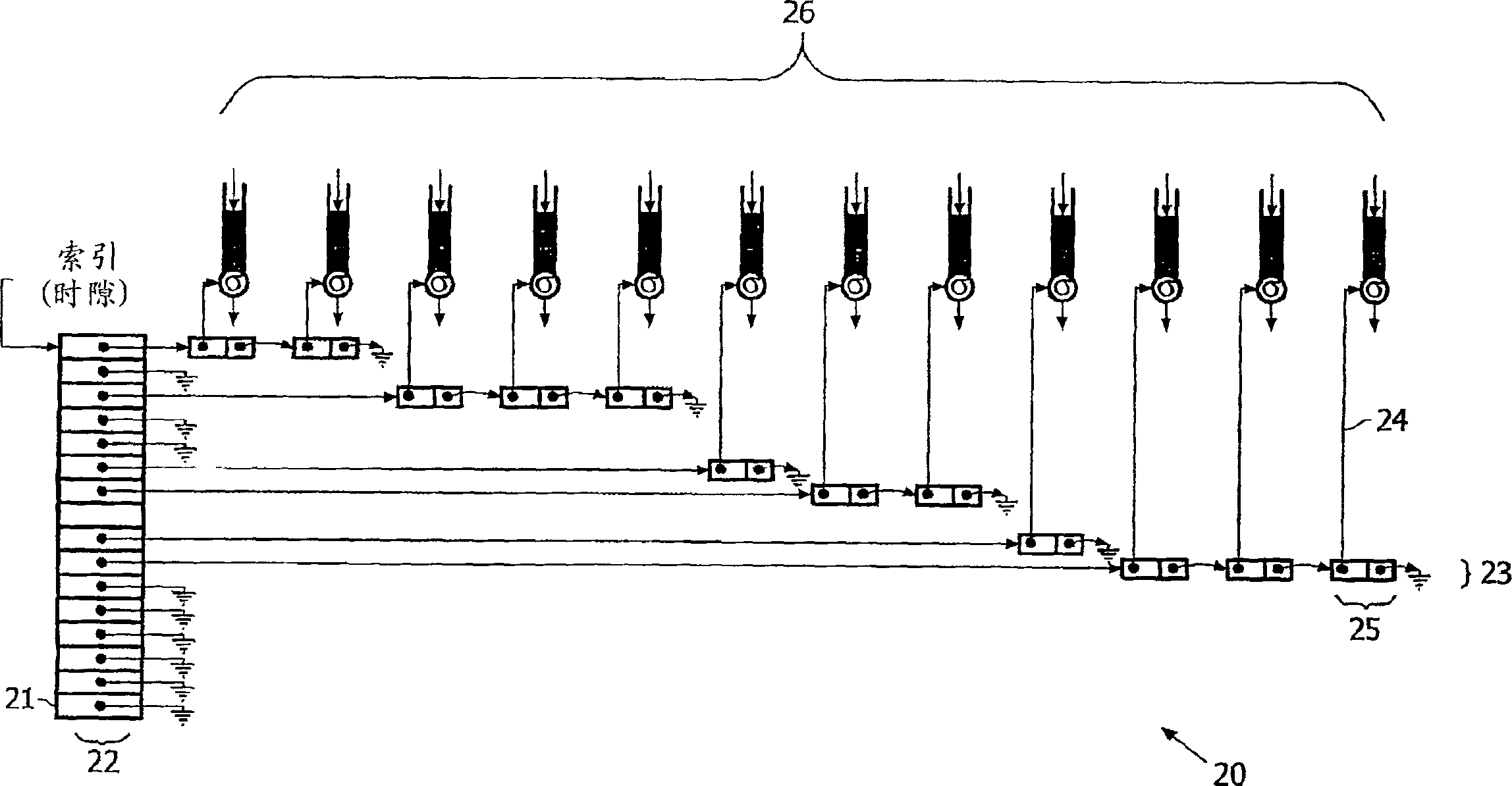
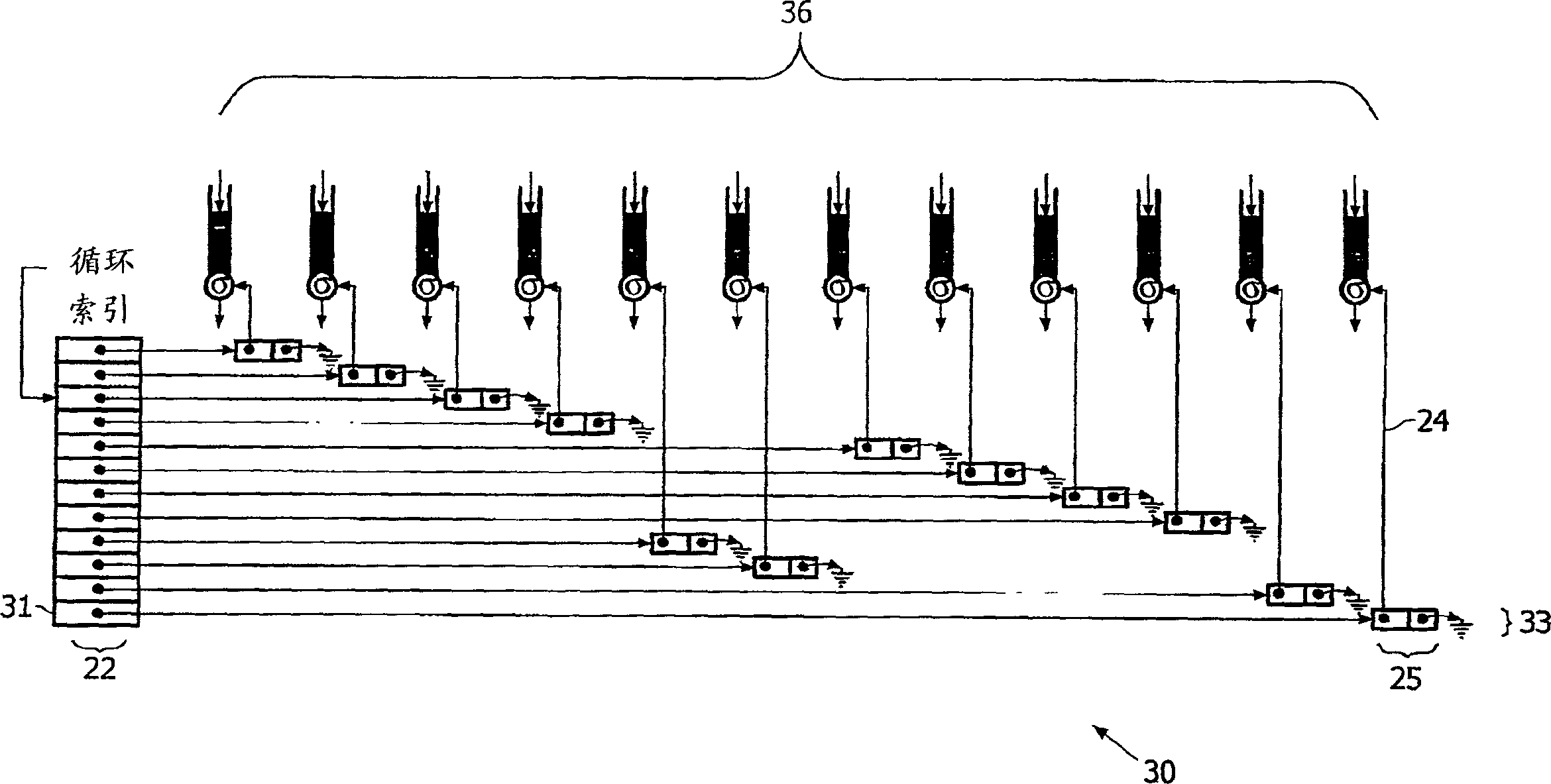
A server has a Guaranteed-Bandwidth (GB) Array 21 and an Extra-Bandwidth (EB) Array 31 with differing quality of Service requirements for transmission of cells held in queues. The server operating to distribute queues around a circular array until there is, at most, one queue per array location in order to minimise cell delay variation.

Description

technical field [0001] The invention relates to a method for scheduling cell transmissions in a server, software and servers for scheduling these cells. Background technique [0002] Traffic managers in Internet routers use servers to schedule the transmission of cells to ensure that cells waiting to be transmitted are dispatched within the required time period, thereby guaranteeing a certain level of service. [0003] By defining an event table by locating events at respective positions in the table (ie, time slots of the timing wheel), events can be scheduled using a table-based timing wheel, enabling searches to be reduced or eliminated. [0004] The schedule can be pre-computed offline, and this is called a static schedule. A dynamic schedule can be implemented by adding one or more events to the timing wheel at appropriate future positions after a specific event has occurred, as in Yun-Sik Lee, Peter M Maurer's "MDCSIM: A Compiled Event- Drive Multidelay Simulator", D...

Claims


Application Information

Patent Timeline
IPC IPC(8): H04L12/56H04L12/54H04L47/525H04L47/56
CPCH04L47/245H04L47/568H04L2012/5664H04L47/525H04L2012/5679H04L47/6215H04L2012/5681H04L12/5693H04L12/5601H04L47/50H04L49/90
Inventor L·A·费茨格拉尔德
Owner KONINKLIJKE PHILIPS ELECTRONICS NV
Learn More