Component feed device
A technology for supplying devices and components, applied in the direction of electrical components, electrical components, etc., can solve problems such as blocking, and achieve the effect of preventing bending, simple structure, and preventing blocking
- Summary
- Abstract
- Description
- Claims
- Application Information
AI Technical Summary
Problems solved by technology
Method used
Image

Examples
Embodiment Construction
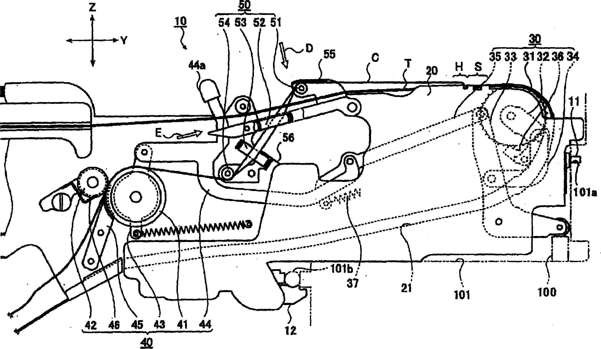
[0027] Hereinafter, embodiments of the present invention will be described in detail with reference to the drawings.
[0028] figure 1 It is a schematic side view showing a part of a parts feeder (parts supplying device) according to one embodiment of the present invention.
[0029] The component feeder 10 of this embodiment is installed on the feeder magazine by inserting the engaging protrusion 11 into the engaging hole of the feeder magazine provided by the electronic component mounting device (not shown), and is similarly installed in parallel. platform for use. exist figure 1 In , a part of the front end side of the parts feeder 10 installed in the feeder magazine is shown.
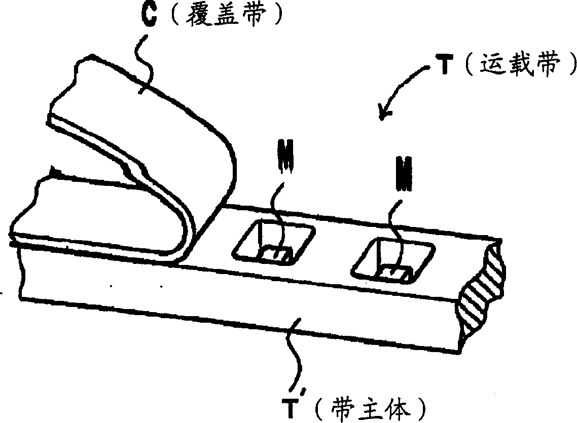
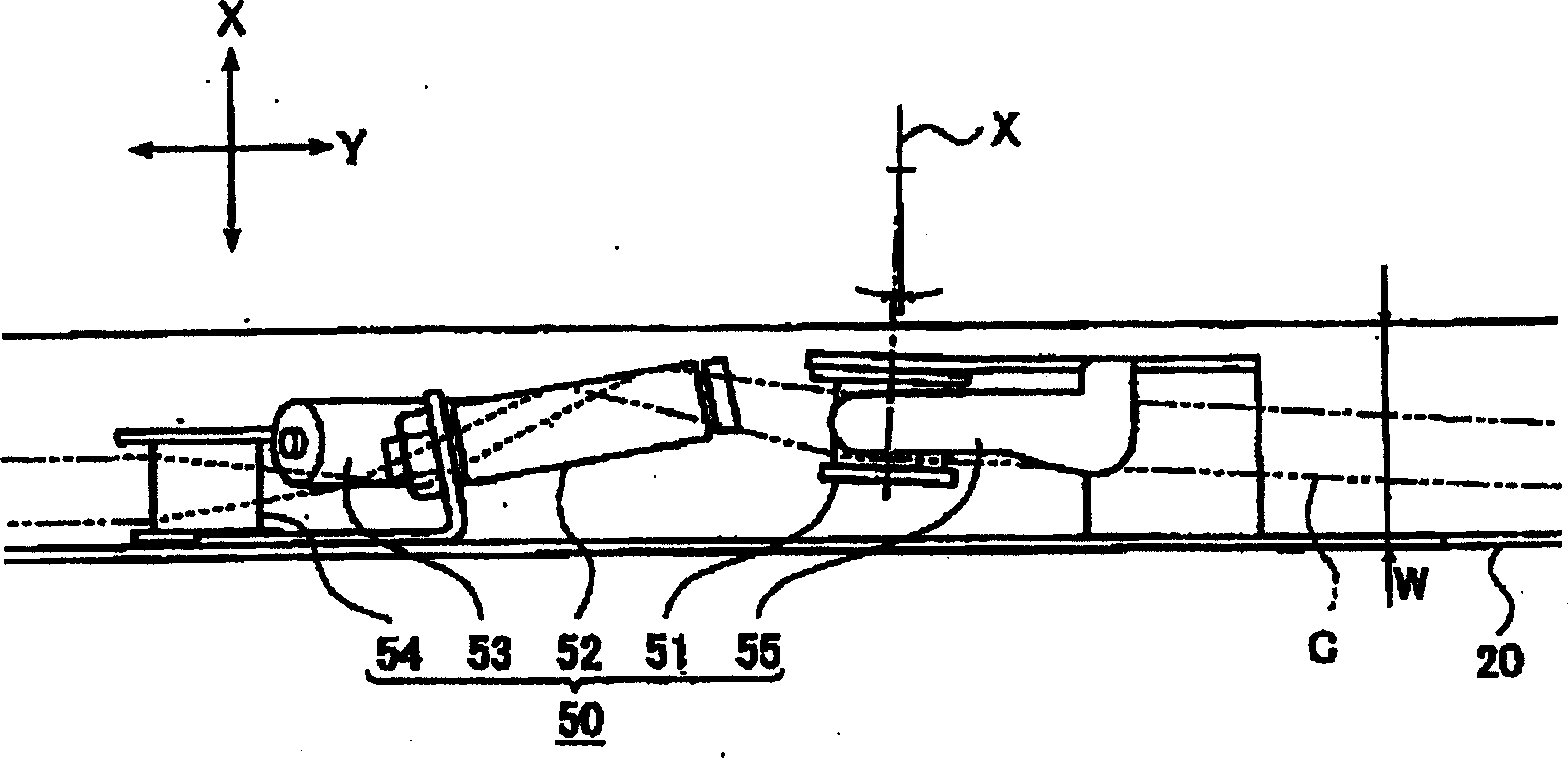
[0030] This component feeder 10 sequentially feeds out the carrier tape T preliminarily wound on the reel from a reel (not shown) held on the rear end side, and moves to the front end side along the conveyance path 21 formed on the frame body 20 . transport. Such as figure 2 As shown in the pa...
PUM
 Abstract
Description
Claims
Application Information
 - Generate Ideas
- Intellectual Property
- Life Sciences
- Materials
- Tech Scout
- Unparalleled Data Quality
- Higher Quality Content
- 60% Fewer Hallucinations
Browse by: Latest US Patents, China's latest patents, Technical Efficacy Thesaurus, Application Domain, Technology Topic, Popular Technical Reports.
© 2025 PatSnap. All rights reserved.Legal|Privacy policy|Modern Slavery Act Transparency Statement|Sitemap|About US| Contact US: help@patsnap.com