Automatic high-cleanness sweeper

A cleaner and high-cleaning technology, applied in the direction of cleaning devices, chemical instruments and methods, cleaning methods and appliances, etc., can solve the problems of material dropping along the belt and broken cutter heads, etc., and achieve good cleaning effect and convenient installation and maintenance , long service life effect

Inactive Publication Date: 2006-10-25
孙付江
View PDF0 Cites 8 Cited by
  • Summary
  • Abstract
  • Description
  • Claims
  • Application Information

AI Technical Summary

Problems solved by technology

Therefore, it is difficult for the cutter head of the cleaner installed to be in contact with the belt to maintain a tight seam. After a few rounds of work, the cutter head will be damaged by the particles adhered to the surface of the belt, and it will also cause Large blanking along the belt

Method used


Image

  • Automatic high-cleanness sweeper
  • Automatic high-cleanness sweeper

Examples


Embodiment Construction

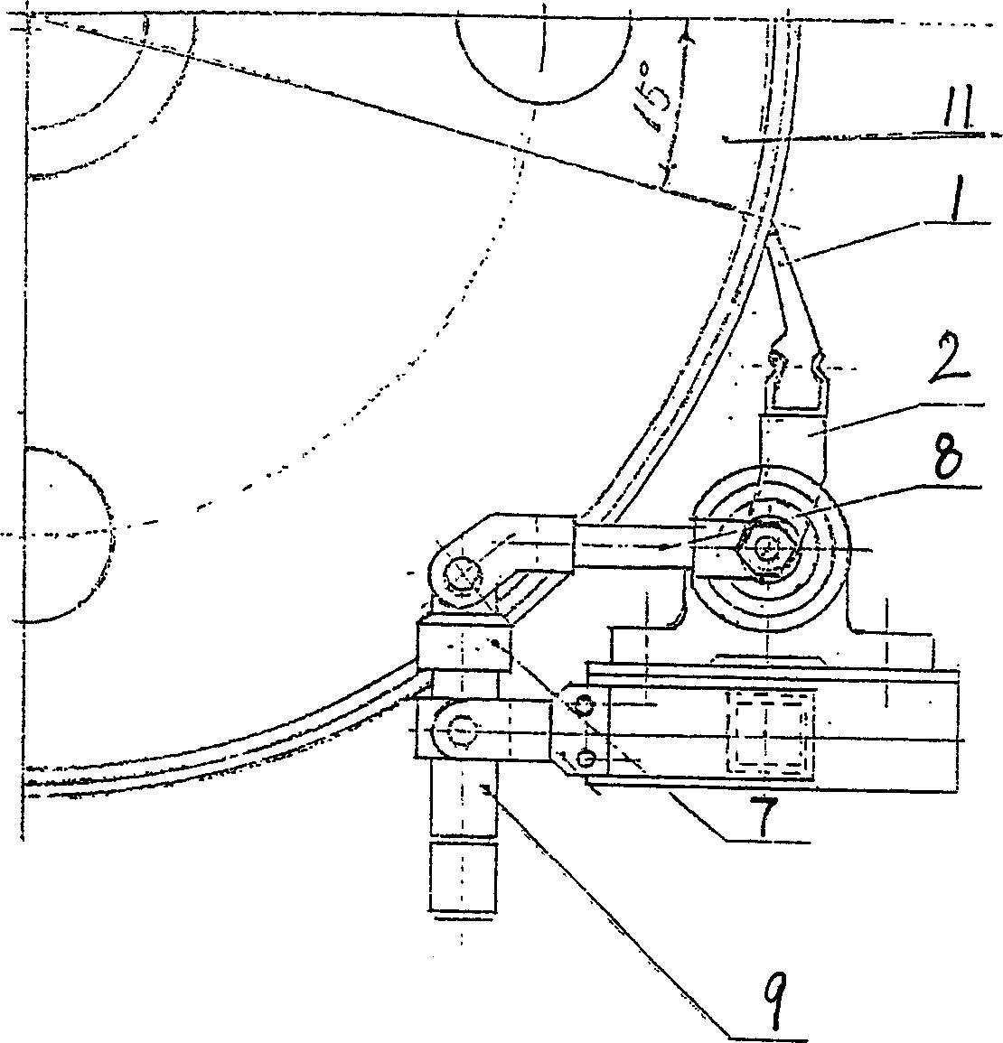
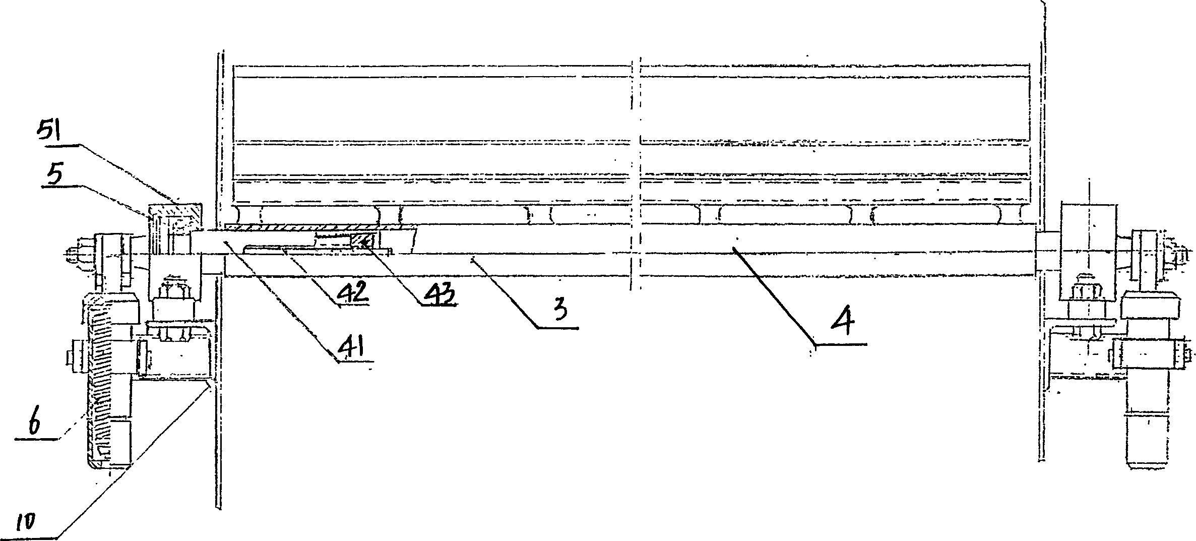
[0021] An automatic high-cleanness cleaner according to the present invention, the knife edge plate 1 is used to install the cutter head, and the cutter head is in close contact with the conveyor belt 11; the knife edge plate 1 is arranged on the beam 2; the beam 2 is fixed on the main shaft 3, The main main shaft 3 is set on the main main shaft 4 and can swing with the main main shaft 4; both ends of the main main shaft 4 are supported by the bearings 5 ​​arranged in the bearing housing 51; the spring 6 arranged in the spring cylinder 9 passes through The extension spring screw rod 7 is connected with one end of the extension spring chain rod 8; the other end of the extension spring chain rod 8 is connected with the master shaft 4 in charge and can make the master shaft 4 in charge swing; the spring cylinder 9 and the bearing seat 51 are fixed on the bracket 10 superior.

[0022] In order to meet different occasions or hoppers with different widths and ensure convenient insta...


PUM


Abstract

The present invention discloses an automatic high-cleanliness cleanser for cleansing powder grains adhered on the conveyer belt. Said cleanser includes the following several portions: blade plate, cross-beam, main pipe shaft, main pipe mother shaft, bearing, spring, extension spring screw rod, extension spring chain bar, spring cylinder body and support. Said invention also provides their connection mode and working priciple of said cleanser.

Description

1. Technical field [0001] The invention belongs to a mechanical product, in particular to an automatic high-purity cleaning device for removing mineral powder adhering to a belt. 2. Background technology [0002] The device for removing the mineral powder adhering to the belt is called a cleaner, and the metal cutter head cleaner is composed of four parts: steel pipe, buffer pad, knife holder and cutter head. The cleaners currently in use mostly use alloy cutter heads. In daily operations, when the metal cutter head cleaner is affected by moisture fluctuations in materials, variety changes, and different belt speeds, its cleaning effect varies greatly, which will cause a lot of material falling along the belt, which is harmful to environmental management. bring difficulty. [0003] For the metal cutter head cleaner, it is required that the moisture content of all transported materials be within 4%, but in actual work, the moisture content of the materials greatly exceeds t...

Claims


Application Information

Patent Timeline
IPC IPC(8): B08B1/00B65G45/10
Inventor 孙付江
Owner 孙付江
Why Eureka
Try Eureka