Fabric guide plate and rise plate linkage mechanism

A technology of linkage mechanism and guide plate, which is applied in knitting, weft knitting, textile and papermaking, etc., can solve the problems of high production cost, many parts and components, complicated mechanism, etc., and achieves low manufacturing cost, reliable work, and guarantees normal work. Effect

Inactive Publication Date: 2006-10-25
冯加林
View PDF0 Cites 4 Cited by
  • Summary
  • Abstract
  • Description
  • Claims
  • Application Information

AI Technical Summary

Problems solved by technology

The existing related mechanism for controlling and driving the guide plate and the guard plate includes a control device, a transmission mechanism and a specially equipped power, so the mechanism is complex, the components are many, and the installation is relatively complicated and the production cost is high.

Method used


Image

  • Fabric guide plate and rise plate linkage mechanism
  • Fabric guide plate and rise plate linkage mechanism
  • Fabric guide plate and rise plate linkage mechanism

Examples


Embodiment Construction

[0013] The present invention will be further described below in conjunction with the accompanying drawings and specific embodiments.

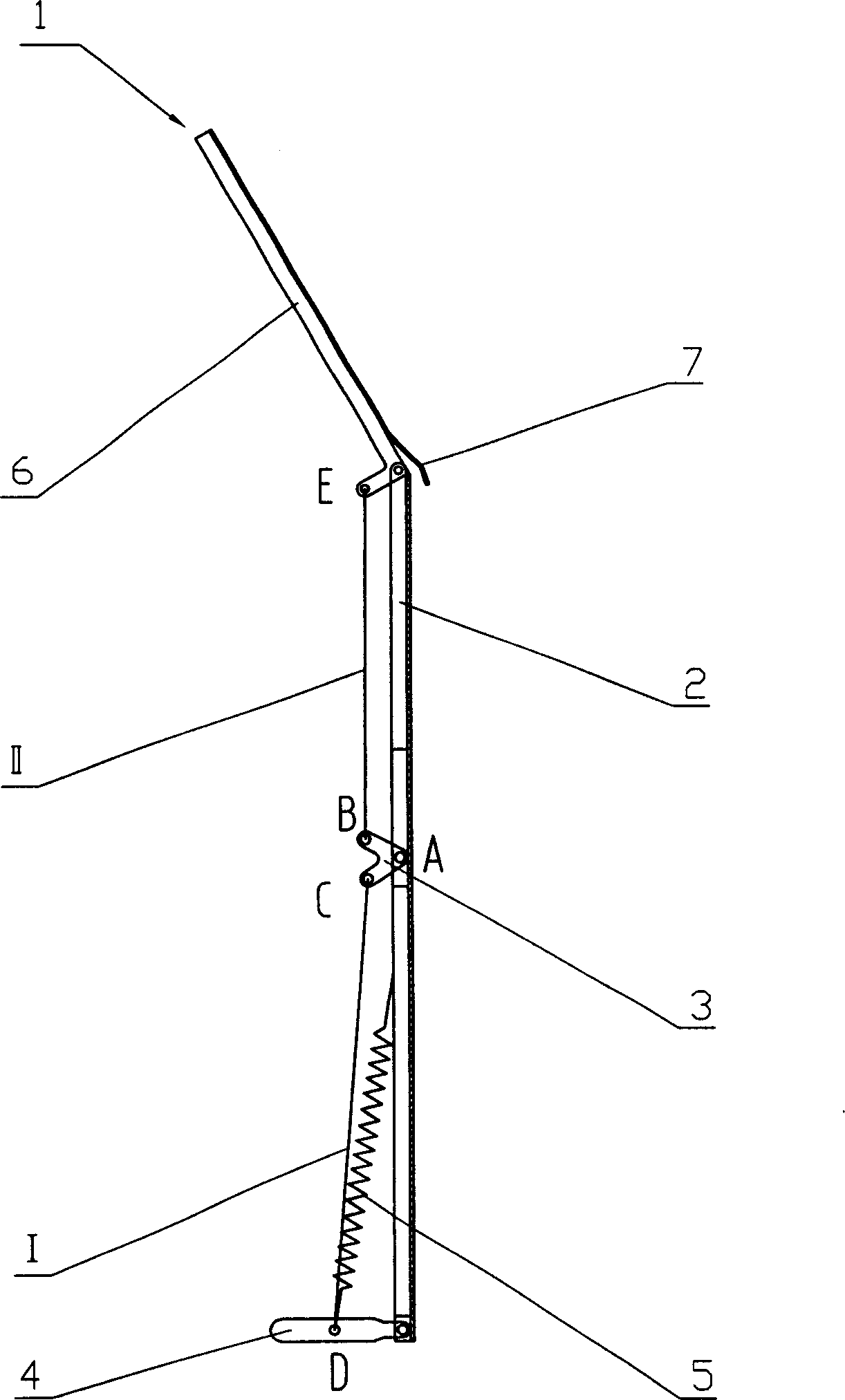
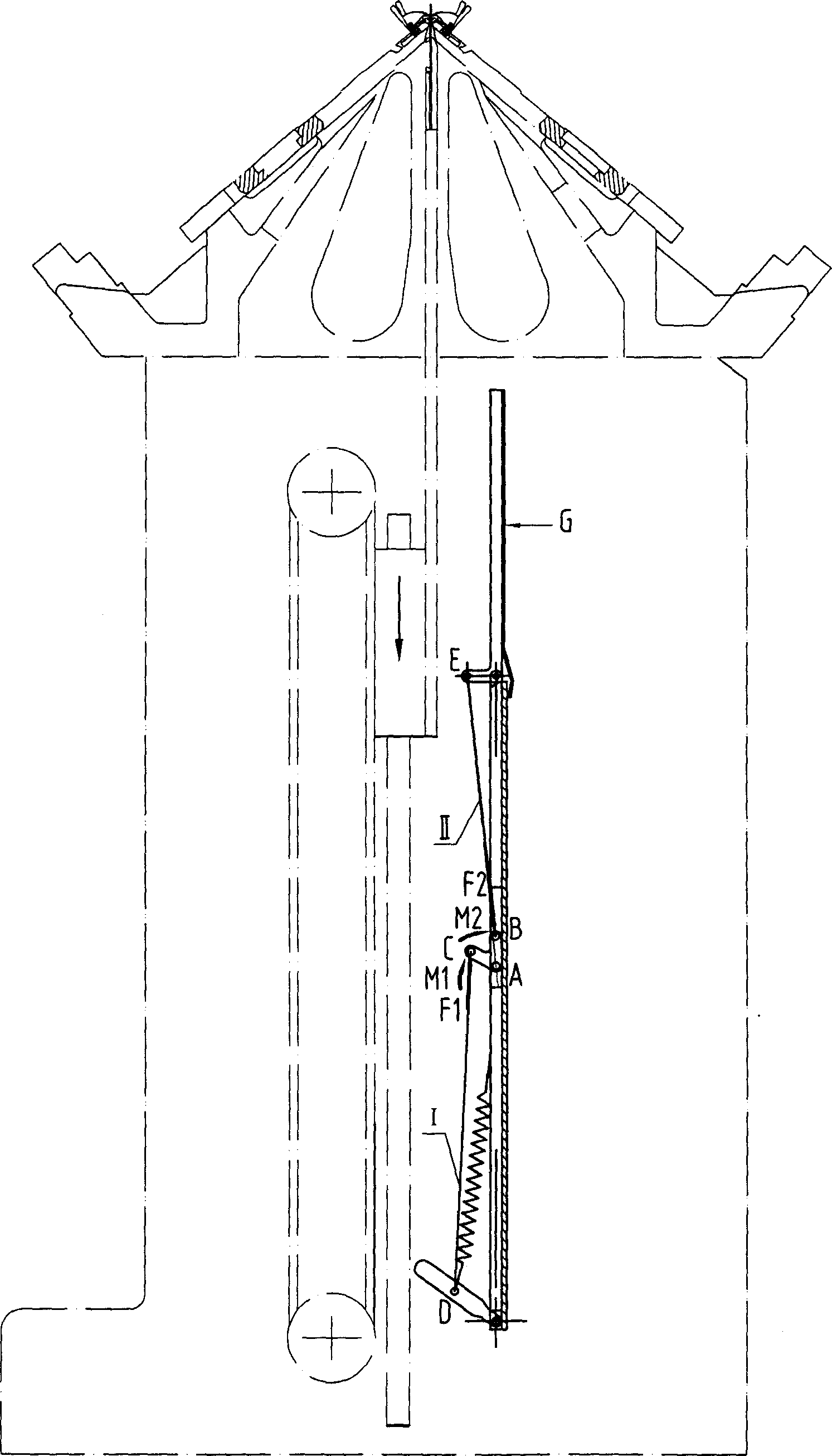
[0014] See figure 1 , The mechanism of the present invention is made up of guide plate 1, guard plate 2, support plate 3, control rod 4, pull rod I, pull rod II and extension spring 5. Wherein the guard plate 2 is installed in the cabinet 15 on the lower side of the flat knitting machine 13, the guard plate 2 is placed on the front side of the needle lifting plate 8, and is located at the position where the sliding hinge seat 10 can be crimped, see figure 2 or image 3 . The upper end of guard plate 2 is hinged with the lower end of guide plate 1, and guide plate can be rotated around its hinge axis, and its range of rotation is from the oblique position of guide plate 1 and horizontal angle about 60 ° to the vertical position. The guide plate 1 is made up of a frame 6 and a panel 7, the panel 7 is connected to one side of the frame 6 by sc...


PUM


Abstract

The invention relates to a fabric guide plate-needle plate linkage mechanism in a flat knitting machine, and its technical solution: it is installed in a machine box on the bottom side of the flat knitting machine, and comprises guide plate, guard plate, support plate, control rod, pull rod I and pull rod II and extension spring, where the guard plate is installed on the front side of the needle plate in the machine box, and the upper end of the guard plate is hinged with the lower end of the guide plate and the guide plate can rotate around a hinge axis between inclined and vertical positions, the support plate is hinged on the guard plate, two ends of the pull rod I are connected with the support plate and control rod, respectively, and two ends of the pull rod II are connected with the support plate and guard plate, respectively, two ends of the extension spring are connected with the control plate and guard plate, respectively. And its advantages: it effectively assures normal operation of the guide plate; the whole linkage mechanism is simple in structure; it has fewer parts, and low manufacturing cost.

Description

technical field [0001] The invention relates to a flat knitting machine, more specifically to a linkage mechanism between a fabric guide plate and a needle lifter in the flat knitting machine. Background technique [0002] In the cabinet on the lower side of the flat knitting machine, a needle lifting plate and a synchronous belt pulley transmission mechanism that drives the needle lifting plate to move up and down are installed, and a guard plate for its safety protection is installed on the front side of the needle lifting plate. When weaving starts, the synchronous pulley drive mechanism makes the needle lifting plate move upwards along the slide rail through the sliding hinge seat until the crochet needles for lifting the needle rise to the upper side of the cylinder mouth for needle lifting knitting. Same as above, the synchronous pulley transmission mechanism drives the needle plate to move downward, and as the knitting continues, the braided fabric grows longer. Since...

Claims


Application Information

Patent Timeline
Patent Type & Authority Applications(China)
IPC IPC(8): D04B15/96
Inventor 冯加林巫友群
Owner 冯加林
Why Eureka
Try Eureka