Surface roughness and/ or contour shape measuring apparatus

A surface roughness and measuring device technology, applied in mechanical roughness/irregularity measurement, measuring device, mechanical counter/curvature measurement, etc., can solve problems affecting the accuracy of measurement, limited objects to be measured, difficulties, etc.

Inactive Publication Date: 2006-10-25
TOKYO SEIMITSU
View PDF1 Cites 20 Cited by
  • Summary
  • Abstract
  • Description
  • Claims
  • Application Information

AI Technical Summary

Problems solved by technology

However, in the case where a workpiece like the crankshaft 100 includes a stepped portion having a dike portion and a bottom (in this case, the crank arms 102a, 102b and the counterweights 103a, 103b form the dike portion, and the crank pin 101 side surface forms the bottom), the cantilever 7 and pick-up 6 are hindered by the crank arms 10a, 102b and counterweights 103a, 103b before the probe 9 comes into contact with the crank pin 101 constituting the surface to be inspected
In this case, it is very difficult to measure the surface roughness of the side surface of the crankpin 101 by conventional surface roughness and / or profile shape measuring devices.
[0011] Also, in the case of using a Y-direction drive unit that moves a workpiece in the Y direction as described above, workpieces whose weight exceeds the limit live load cannot be measured, and thus can be measured by such a surface roughness and / or contour shape measuring device. Objects for measurement are limited
[0012] Moreover, the deformation and driving operation of the movable table are affected by the position of the center of gravity, so the amount of displacement also changes with the center of gravity or installation position of the workpiece, thereby affecting the accuracy of measurement
[0013] In order to ensure a predetermined active load, the Y-direction drive unit of the workpiece needs to use a mechanism or power supply with a corresponding capacity margin, resulting in a bulky and expensive surface roughness and / or profile shape measuring device
[0014] In addition, in the case where the Y-direction drive unit is placed on the table, there is a column between the Y-direction drive unit and the drive unit 4, which makes it difficult to place the Y-direction drive unit exactly perpendicular to the drive unit 4. , due to the influence of temperature changes and vibration

Method used


Image

  • Surface roughness and/ or contour shape measuring apparatus
  • Surface roughness and/ or contour shape measuring apparatus
  • Surface roughness and/ or contour shape measuring apparatus

Examples


Embodiment Construction

[0035] Preferred embodiments of the present invention will be described in detail below with reference to the accompanying drawings.

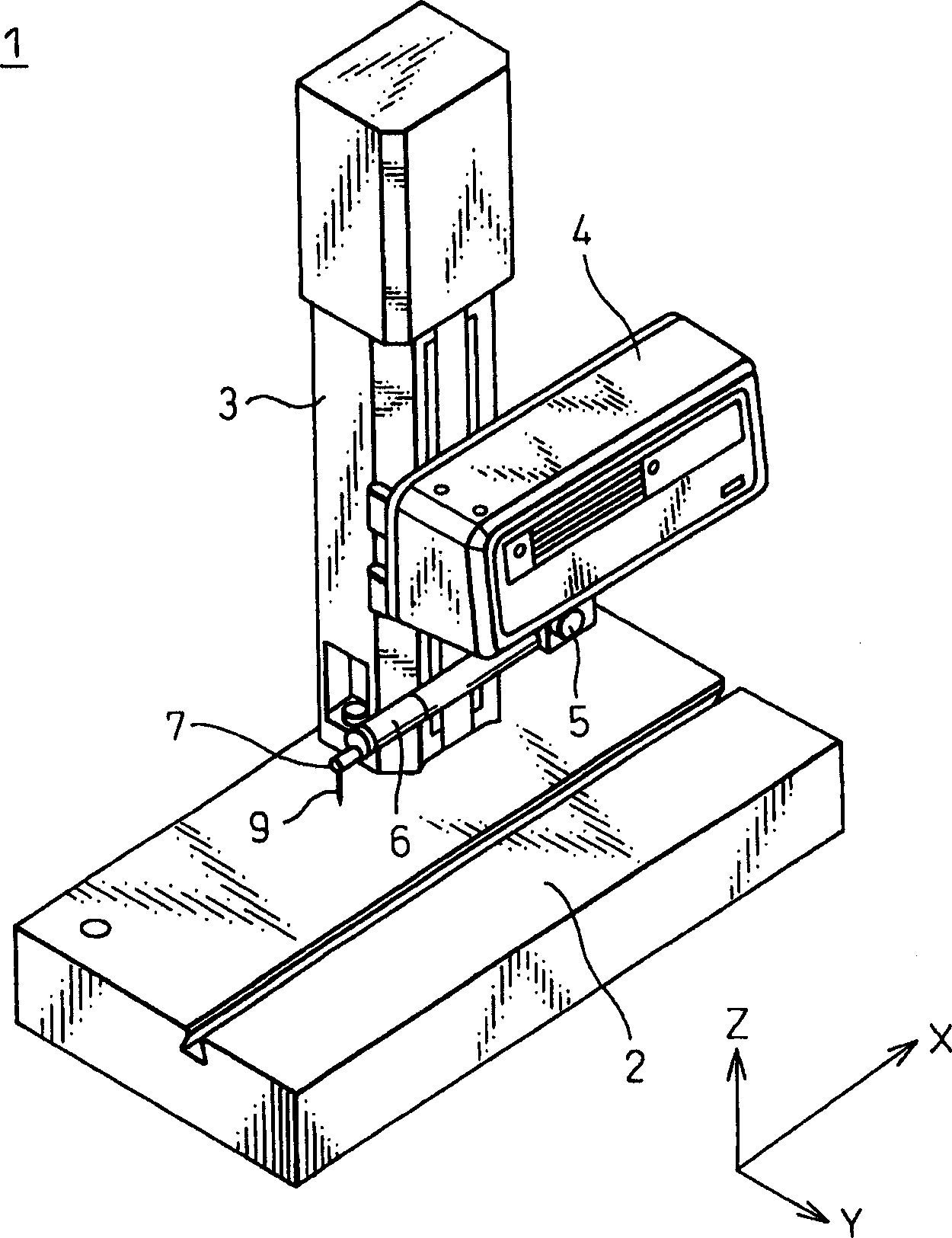
[0036] Figure 4 A basic configuration of a surface roughness and / or profile shape measuring device according to an embodiment of the present invention is shown. The basic structure of this surface roughness and / or profile shape measuring device 1 and figure 1 The shown configurations are similar, and the same functional components in these figures are respectively assigned the same reference numerals, and the explanation will not be repeated.

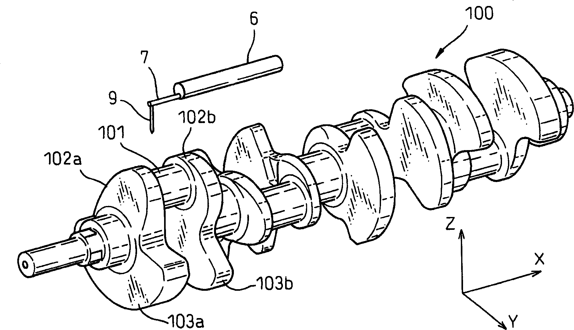
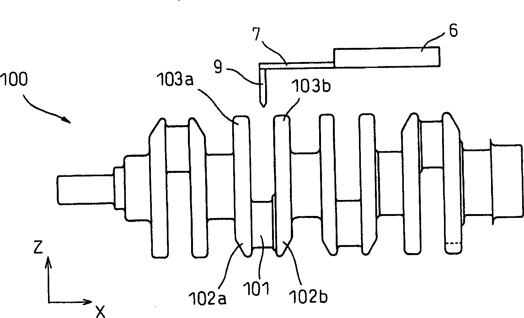
[0037] Such as Figure 4 As shown, in the surface roughness and / or profile shape measuring device 1, the pickup 6 and the cantilever 7 are installed so that their length direction is along the X direction, that is, the probe 9 is driven by the drive unit 4 on the table surface in the XY plane The direction of the drive. The probe 9 is mounted on the front end of the cantilever 7 so as to extend alon...


PUM


Abstract

A surface roughness and / or contour shape measuring apparatus for measuring the surface shape of a work measurement surface by moving a probe supported on a cantilever and kept in contact with the work measurement surface and by detecting the displacement amount of the probe is disclosed. The surface roughness and the contour shape of a stepped work bottom portion having bank portions and the bottom portion can be easily measured. The surface roughness and / or contour shape measuring apparatus (1) includes a moving unit (8) for moving the work and the probe (9) relatively to each other in the direction (X) perpendicular to both the longitudinal direction (Z) of the probe (9) and the longitudinal direction (Y) of the cantilever (7).

Description

technical field [0001] The present invention relates to a surface roughness and / or profile shape measuring device, or in particular to a surface roughness and / or profile shape measuring device for measuring the surface roughness and / or profile shape of an object in two directions. Background technique [0002] In the surface roughness and / or profile shape measuring device, a pickup having a probe moves along the surface of an object to be measured (hereinafter generally referred to as a "workpiece"), and the displacement amount of the probe is converted into an electrical signal and Read by a computer or similar device to measure the surface roughness and / or contour shape of the workpiece. Such a surface roughness and / or profile shape measuring device is disclosed in Unexamined Japanese Patent Application No. 2002-107144. figure 1 The basic configuration of a conventional surface roughness and / or profile shape measuring device is shown. [0003] The surface roughness and / o...

Claims


Application Information

Patent Timeline
Patent Type & Authority Applications(China)
IPC IPC(8): G01B21/30G01B21/20
CPCG01B5/20G01B5/28
Inventor 谷内信幸久保田和浩
Owner TOKYO SEIMITSU
Why Eureka
Try Eureka