Electronic sphygmomanometer

An electronic sphygmomanometer and blood pressure measurement technology, applied in vascular assessment, cardiac catheterization, etc., can solve the problem of time-consuming, may not achieve complete relaxation, and achieve the effect of improving measurement accuracy, relieving psychological tension, and improving accuracy

Inactive Publication Date: 2006-11-01
JINLING ELECTRICAL CO LTD
View PDF2 Cites 3 Cited by
  • Summary
  • Abstract
  • Description
  • Claims
  • Application Information

AI Technical Summary

Problems solved by technology

Such a regulation is mainly to let the subject be in a relaxed state, but it is obviously t

Method used


Image

  • Electronic sphygmomanometer
  • Electronic sphygmomanometer
  • Electronic sphygmomanometer

Examples


Example Embodiment

[0018] The electronic sphygmomanometer of the embodiment of the present invention is improved on the basis of an electronic sphygmomanometer in the prior art. For the design of the electronic sphygmomanometer in the prior art, please refer to the Chinese invention patent ZL93109916.1 specification CN1050040C "Electronic Sphygmomanometer". The following mainly introduces the design of the differences between the electronic sphygmomanometer according to the embodiment of the present invention and the electronic sphygmomanometer. For the unintroduced designs, please refer to the contents in the manual CN1050040C "Electronic Sphygmomanometer" of ZL93109916.1.

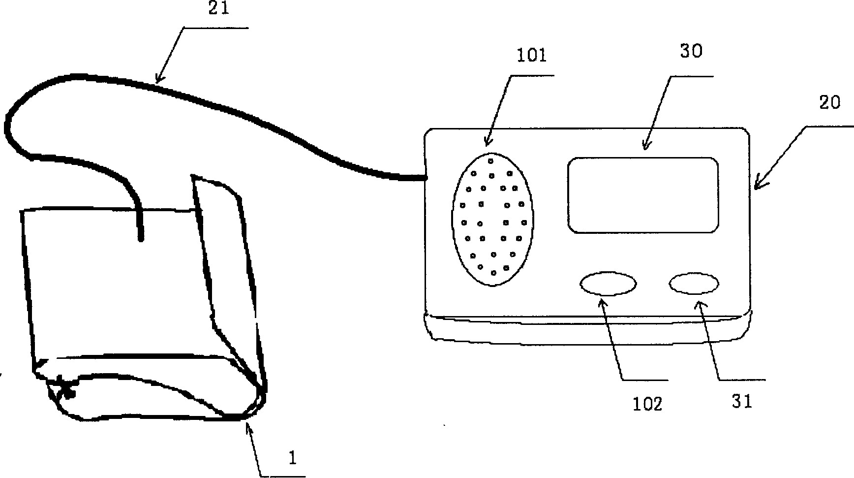
[0019] The appearance of the electronic sphygmomanometer according to the embodiment of the present invention is shown in figure 1 , including: air cuff 1, rubber ball 2 for manually increasing the air pressure in the air cuff, pressure regulating valve 3 for slowly releasing the air in the air cuff, the main body 20 of the...


PUM


Abstract

An electronic hematomanometer is composed of a pressure sleeve, a pressurizing unit for increasing the internal pressure of said pressure sleeve, a pressure releasing unit, a pressure sensor for converting the pressure to electric signal, a microcomputer with I/O device, and a sound device connected to output of said microcomputer for reproducing light music to relax the spirit of the person to be tested, resulting in high precision.

Description

technical field [0001] The invention relates to an electronic sphygmomanometer, which belongs to A61B5 / 022 in the international patent classification table. Background technique [0002] Sphygmomanometers are no strangers to many people. In addition to the traditional mercury sphygmomanometer that uses auscultation to measure commonly used in hospitals, electronic sphygmomanometers that use sensors and electronic circuits are common in home health care. The typical design of the latter can be found in Chinese invention patent ZL93109916. 1 Instructions CN1050040C "Electronic Sphygmomanometer". Whether using a mercury sphygmomanometer or an electronic sphygmomanometer to measure blood pressure, according to medical requirements, in order to achieve accurate blood pressure measurement, the person being measured should maintain a good posture and let the muscles of the whole body relax; The height is at the same level as the heart. The bottom of the cuff of the arm-type elect...

Claims


Application Information

Patent Timeline
IPC IPC(8): A61B5/022A61B5/0225
Inventor 卓春光
Owner JINLING ELECTRICAL CO LTD
Why Eureka
Try Eureka