Inflation tire

A technology of pneumatic tires and tire radius, applied in tire parts, tire tread/tread pattern, transportation and packaging, etc., can solve the problem of insufficient water film suction effect, etc., to improve suction effect and improve driving performance , the effect of preventing occlusion

Inactive Publication Date: 2006-11-01
SUMITOMO RUBBER IND LTD
View PDF1 Cites 30 Cited by
  • Summary
  • Abstract
  • Description
  • Claims
  • Application Information

AI Technical Summary

Problems solved by technology

[0004] However, if Figure 12 As shown, it has been found that in the conventional sipe S, when the block B is in contact with the road surface to receive the shear force F, in the portion A close

Method used


Image

  • Inflation tire
  • Inflation tire
  • Inflation tire

Examples


Example

[0068] (Examples 1~2)

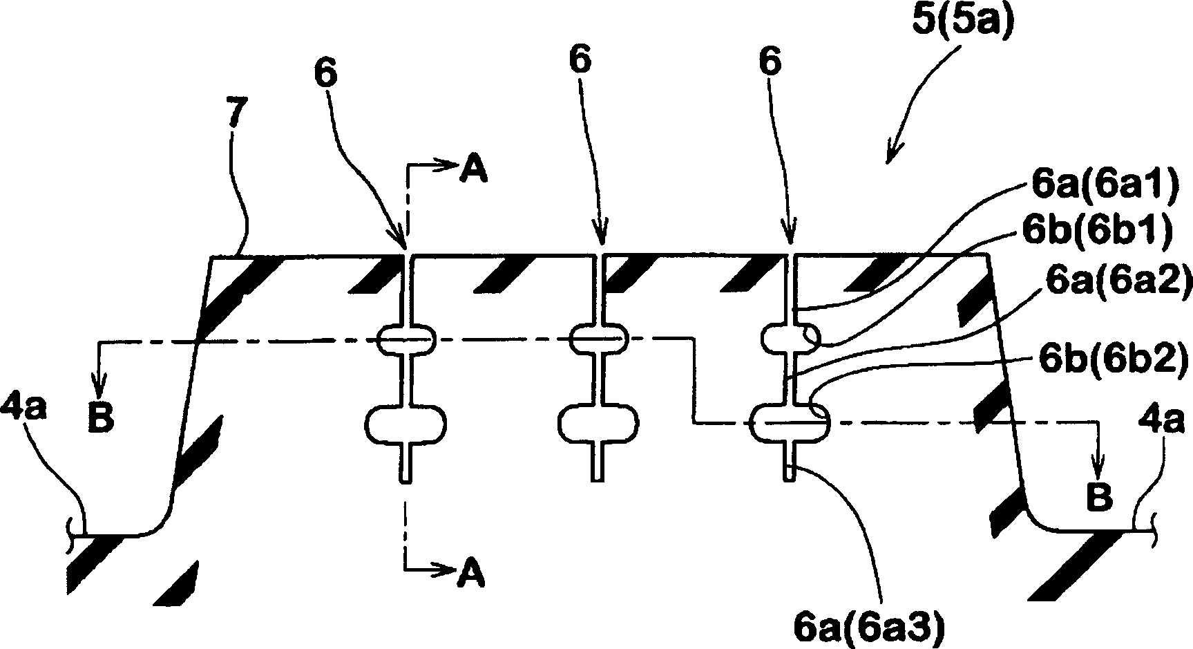
[0069] In Example 1 and Example 2, in all the blocks, set the Picture 11 The dimension X of (A) is set to a semi-open sipe-like narrow groove 0.7 times the block width BW. In Example 1, one widened part was provided in one sipe-like narrow groove, and in Example 2, two widened parts were provided. The widened parts are all arranged in the aforementioned area Y.

Example

[0070] (Examples 3~6)

[0071] In Examples 3 to 6, in all the blocks, the Picture 11 The dimension X of (A) is set to a full-open sipe-like narrow groove 1.0 times the block width BW. In Example 3, one widened portion is provided in one sipe-like narrow groove. In Examples 4 and 5, two widened portions are provided, and in Example 6, three widened portions are provided. In Example 5, the widened portion flared the diameter from the center side of the block in the width direction toward the side edge side. The widened parts are all arranged in the aforementioned area Y.

Example

[0072] (Conventional examples, comparative examples 1 to 2)

[0073] In the conventional example, a sipe without a widened portion is provided. The sipe pattern is the same as the sipe pattern of each embodiment. Comparative Example 1 is based on Example 1, but the widened portion is provided outside the region Y, and the widened portion of Comparative Example 2 is located further inward in the radial direction than the region Y.

[0074] The common specifications of each example are as follows.

[0075] Block height BH: 10.0mm

[0076] The maximum depth of the sipe-like narrow groove: D=8.0mm

[0077] Maximum depth of sipe (conventional example): 10.0mm

[0078] Groove width g of the sipe part: 1.0mm


PUM


Abstract

PROBLEM TO BE SOLVED: To provide a pneumatic tire capable of enhancing water-absorbing effect on an ice road and improving traveling performance. Ž

SOLUTION: The pneumatic tire is provided with a plurality of longitudinal grooves 3 extending to the tire circumferential direction on a tread part. The pneumatic tire has land parts 5 between adjacent longitudinal grooves 3, 3 or between the longitudinal groove 3 and the tread end. The land part 5 is provided with a siping shape narrow groove 6 which extends to the direction crossing the land part 5, at least one end 6E is communicated to the longitudinal groove 3 or the tread end, and opens at the ground surface 7. The siping shape narrow groove 6 comprises a sipe part 6a having an incised shape groove width of 2.0 mm or less, and an expanded width part 6b which is continued to the inward radial direction of the sipe part 6a and has the groove width of more than 2.0 mm. The expanded width 6b is provided at the area Y where the maximum depth D of the siping shape narrow groove from the ground surface 7 is not less than 20% and not more than 90%. Ž

COPYRIGHT: (C)2007,JPO&INPIT Ž

Description

technical field [0001] The present invention relates to a pneumatic tire capable of improving running performance on icy roads. Background technique [0002] Conventionally, for example, various types of studless tires have been proposed as winter tires whose main purpose is to run on icy and snowy roads (for example, refer to the following Patent Document 1). In these pneumatic tires, convex portions such as blocks and ribs are provided on the tread portion, and groove-shaped sipes having small groove widths are provided on the convex portions at intervals. The role of the sipe can be listed as follows: first, to increase the edge component, second, to achieve moderate softening of the block rigidity, and third, to use capillary phenomenon to absorb the water film on the icy road surface to improve friction etc. [0003] [Patent Document 1] JP Unexamined Patent Publication No. 8-104111 [0004] However, if Figure 12 As shown, it has been found that in the conventional s...

Claims


Application Information

Patent Timeline
IPC IPC(8): B60C11/13
CPCB60C11/1281
Inventor 山西照明
Owner SUMITOMO RUBBER IND LTD
Why Eureka
Try Eureka