
Deformable lens and optical pickup device including same

A technology for deformable mirrors and mirrors, which is applied in the field of optical pick-up devices and mirror shape changes, and can solve the problems of small expansion and shrinkage of piezoelectric elements and increase the shape change of mirror parts, etc.

Inactive Publication Date: 2006-11-01
FUNAI ELECTRIC CO LTD
View PDF2 Cites 4 Cited by
  • Summary
  • Abstract
  • Description
  • Claims
  • Application Information

AI Technical Summary

Problems solved by technology

In this regard, for the deformable mirrors disclosed in the aforementioned JP-A-2004-70004 and JP-A-2004-347753, although it is proposed to improve the shape change efficiency of the mirror part under a given applied voltage, the voltage The amount of expansion and contraction of the electric element itself is very small, so under a given applied voltage, improving the shape change efficiency of the mirror part does not have a great effect on increasing the shape change of the mirror part
[0008] The amount of expansion and contraction of piezoelectric elements can be increased by laying them in multiple layers, but deformable mirrors incorporated in optical pickup devices have little room for increase

Method used


Image

  • Deformable lens and optical pickup device including same
  • Deformable lens and optical pickup device including same
  • Deformable lens and optical pickup device including same

Examples


Embodiment Construction

[0031] Embodiments of the present invention will be described below with reference to the drawings. It should be understood that the embodiments described below are only examples, and therefore do not represent any limitation on the way of implementing the present invention. It should also be understood that in the drawings, the size and thickness of each component, the amount of shape change when the shape changes, etc., are exaggerated for the purpose of easy understanding, so these dimensions are not the same as the actual observed size. same.

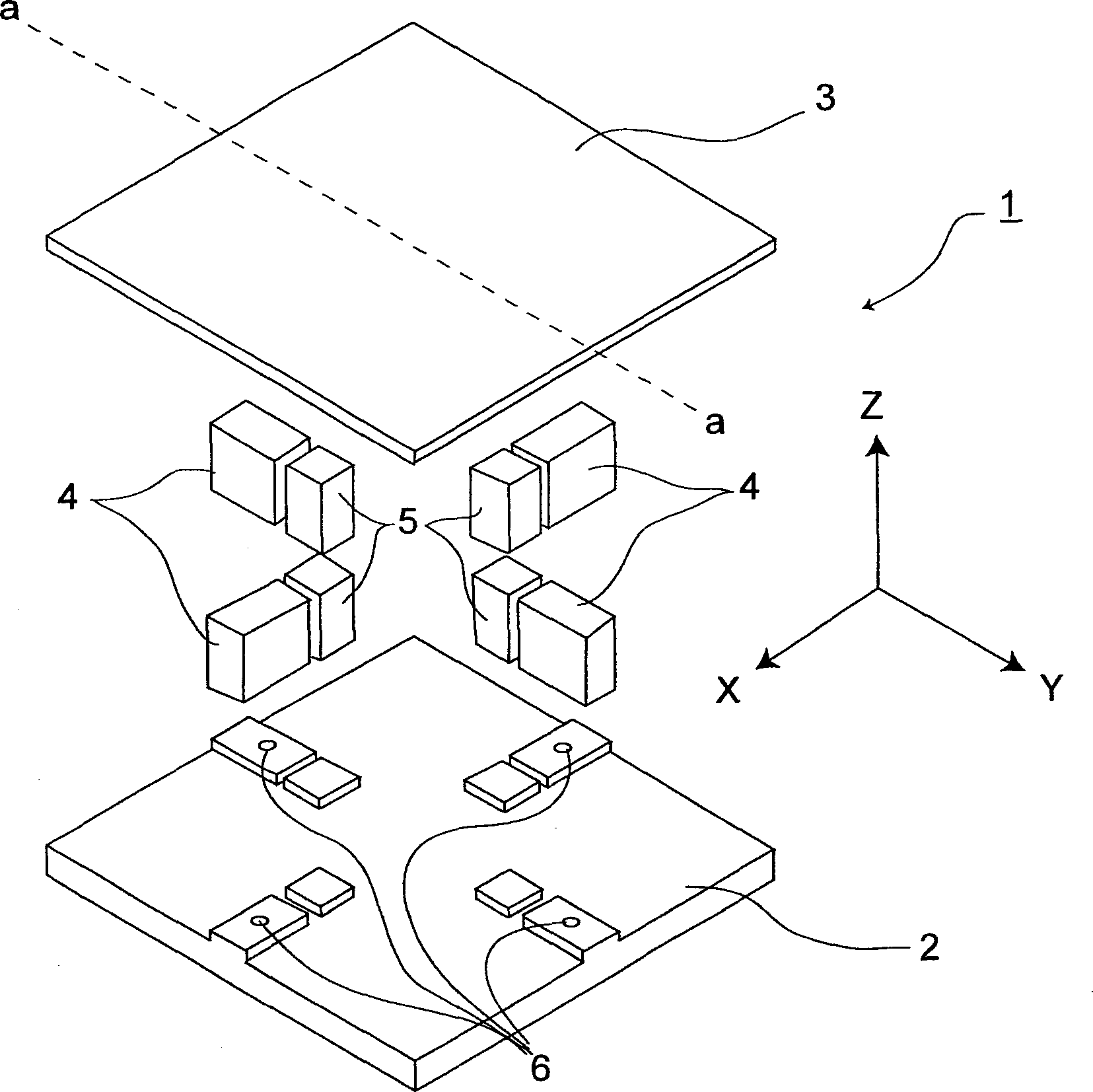
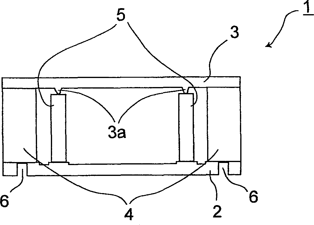
[0032] Figure 1A The schematic diagram of shows the structure of the deformable mirror as an embodiment of the present invention, which shows its components in an exploded perspective view. Figure 1B is along Figure 1A A cross-sectional view cut along the line a-a in the middle.


PUM


Abstract

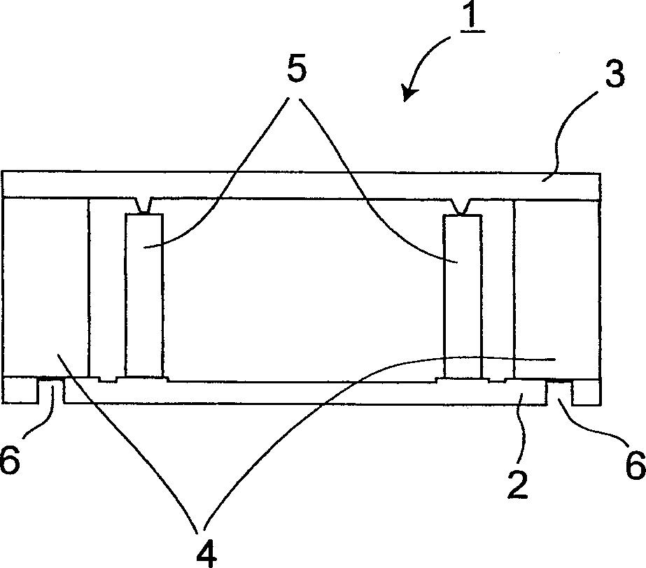
In a variable-shape mirror ( 1 ) of which the shape of the mirror surface can be varied, four piezoelectric elements ( 4 ) are sandwiched between a support base ( 2 ) and a mirror portion ( 3 ), and are arranged symmetrically in cross-shaped directions. The piezoelectric elements ( 4 ) are bonded to the mirror portion ( 3 ), and serve both to vary the shape of the mirror portion ( 3 ) by being driven and to fix the mirror portion ( 3 ) to the support base ( 2 ). Support portions ( 5 ) are arranged one inside each of the piezoelectric elements ( 4 ). With this structure, a small movement that the piezoelectric elements ( 4 ) produce when driven can be converted into a large movement of the mirror portion(3).

Description

technical field [0001] The invention relates to a deformable mirror capable of changing the shape of its mirror surface, in particular to the amount of shape change of the mirror surface of the deformable mirror. The invention also relates to an optical pickup device provided with a deformable mirror. Background technique [0002] When using an optical pickup to read or write information from or to an optical disc such as a CD (Compact Disc) or DVD (Digital Versatile Disc), the relationship between the optical axis of the optical pickup and the disc surface should theoretically be vertical. In reality, however, their relationship does not always remain perpendicular as the disk rotates. As a result, for an optical disc such as a CD or DVD, when the disc surface becomes inclined with respect to the optical axis, the optical path of the laser light is bent to generate coma aberration. [0003] When coma aberration occurs, the laser spot irradiated on the optical disk deviat...

Claims


Application Information

Patent Timeline
Patent Type & Authority Applications(China)
IPC IPC(8): G02B26/08G02B7/182G11B7/095G11B7/135
CPCG02B7/1822G02B26/0825
Inventor 长岛贤治藤井仁田中史记杉山进石井明田中克彦久濑亘
Owner FUNAI ELECTRIC CO LTD
Learn More