Remote electric power supplying system and its control

A remote power supply and remote technology, applied in the field of remote power supply, can solve the problems of wasting network resources and insecurity, and achieve the effect of saving network resources, energy and line resources.

Active Publication Date: 2006-11-01
HUAWEI DIGITAL POWER TECH CO LTD
View PDF0 Cites 6 Cited by
  • Summary
  • Abstract
  • Description
  • Claims
  • Application Information

AI Technical Summary

Problems solved by technology

[0007] The purpose of the present invention is to provide a remote power supply system and its power-on control method to overcome the shortcomings of unsafe power-on process and waste of network resources in the prior art

Method used


Image

  • Remote electric power supplying system and its control
  • Remote electric power supplying system and its control
  • Remote electric power supplying system and its control

Examples


Embodiment Construction

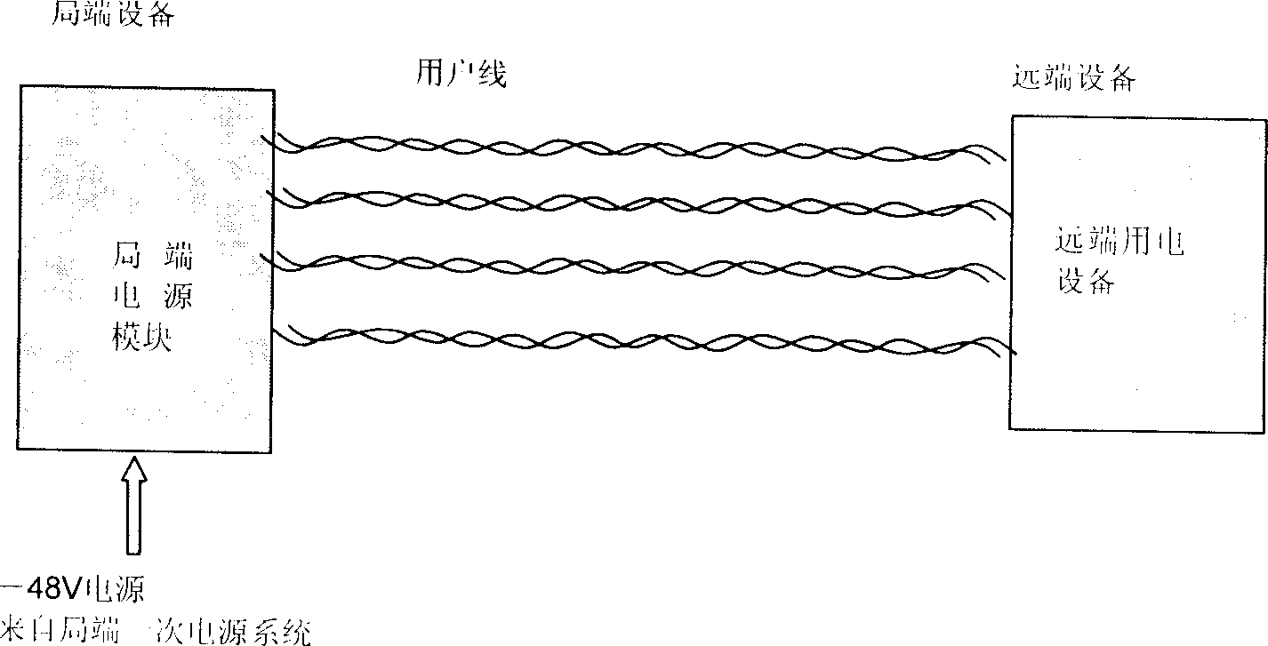
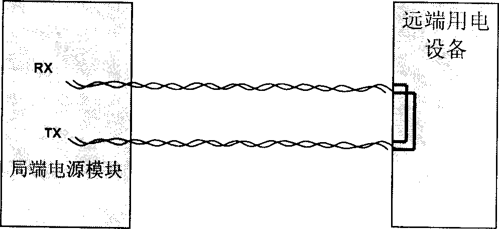
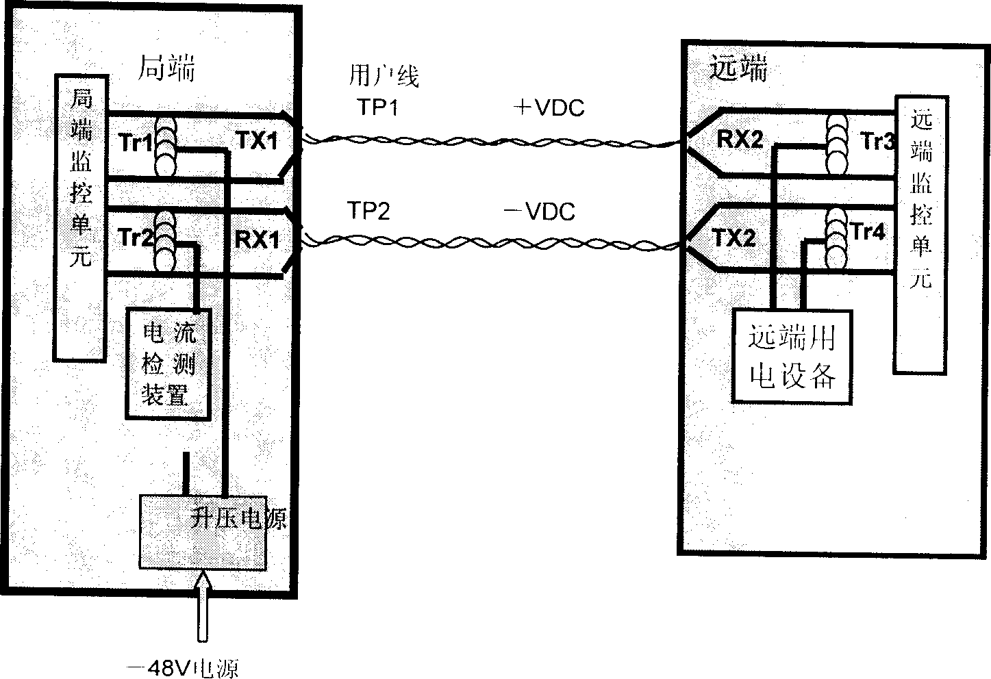
[0046]The remote power supply system in the communication system provided by the present invention mainly includes: a local end power supply part for supplying power to remote power consumption equipment, the local end power supply part includes a local end monitoring unit and a local end power supply module, and the remote power supply The device is provided with a remote monitoring unit; the remote monitoring unit monitors the presence status of the remote user equipment, and transmits a monitoring signal of the presence status information of the remote user equipment to the central office monitoring The local-end monitoring unit controls the local-end power module to provide power for the remote power-consuming equipment according to the on-position status information.

[0047] The remote power supply system and its power-on control method provided by the present invention will be further described in detail below in conjunction with the accompanying drawings.

[0048] atta...


PUM


Abstract

The system thereof comprises: a power supply at central office end for providing power for remote power consumer at remote end. Said power supply comprises: central office monitoring module and central office power module. A remote end monitor is set in the remote power consumer. Said remote end monitor monitors the on-line state of said remote power consumer, and sends the monitor signal to said central office monitor module. By the monitor signal from the remote monitor, the central office monitor module controls the central office power supply module to provide power for the remote power consumer.

Description

technical field [0001] The invention relates to a power supply technology in a communication system, in particular to a remote power supply technology in a communication system. Background technique [0002] With the rapid development of network communication systems, remote power supply systems have become an important technology in expanding communication services. For example, in the case of the ever-increasing demand for XDSL (X Digital Subscriber Line) services, a relatively common method to expand new services to end users on the basis of the existing digital subscriber line network is: to use DSLM ( DSL Access Multiplexer, DSL access multiplexer) equipment is more moved to the end user side. In this way, 1-2 pairs of twisted pairs or coaxial cables can be used as the uplink channel, and more users and services can be accessed through the DSLM equipment. Since the environment on the user side is complex and it is inconvenient to provide power in most cases, moving th...

Claims


Application Information

Patent Timeline
Patent Type & Authority Applications(China)
IPC IPC(8): H04L12/10
Inventor 潘雪峰秦真蒋天利周英杰
Owner HUAWEI DIGITAL POWER TECH CO LTD
Why Eureka
Try Eureka