
Spiral material taking device

A reclaimer and screw technology, applied in the direction of conveyor objects, transportation and packaging, loading/unloading, etc., can solve the problems of adding reclaimers, ordinary reclaimers can not normally reclaim materials, and increasing the weight of the front end of reclaimers, etc.

Inactive Publication Date: 2006-11-15
钱尧翎
View PDF0 Cites 3 Cited by
  • Summary
  • Abstract
  • Description
  • Claims
  • Application Information

AI Technical Summary

Problems solved by technology

If you want to increase the amount of reclaimed material at one time, you must increase the volume of the reclaimed hopper and increase the weight of the front end of the reclaimer
At the same time, when the bulk material is about to be loaded and unloaded and only a small part is left, the ordinary reclaimer cannot take the material normally at all.

Method used


Image

  • Spiral material taking device
  • Spiral material taking device
  • Spiral material taking device

Examples


Embodiment Construction

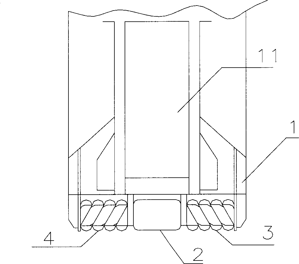
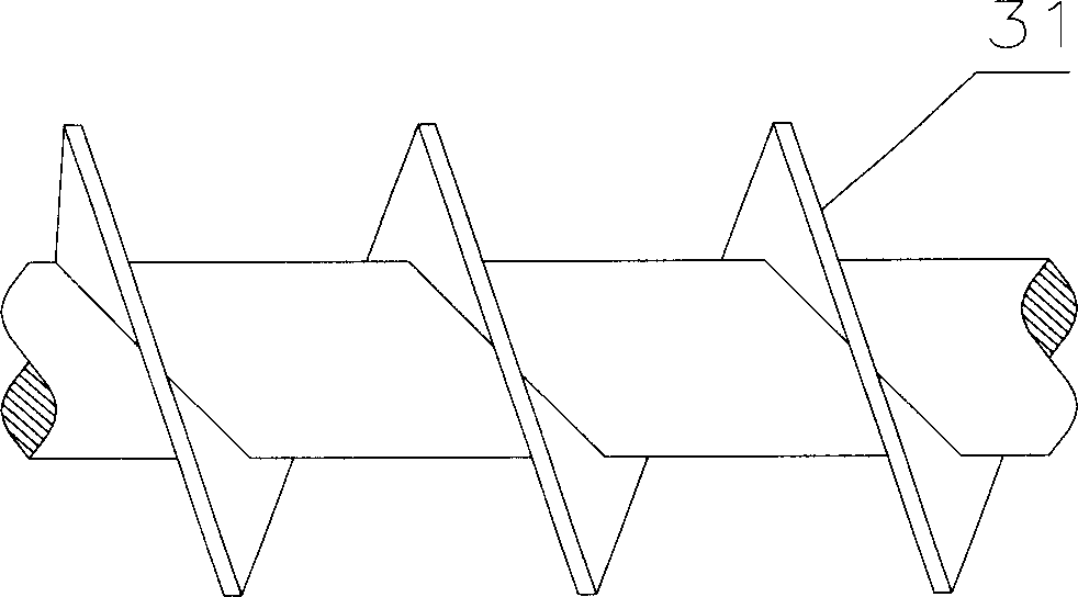
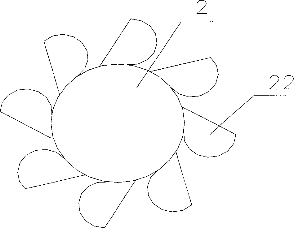
[0010] Such as figure 1 , 2 , 3, the present invention includes a bucket wheel 2 with a throwing bucket 22 arranged on the front end 1 of the reclaimer, and the two sides of the bucket wheel 2 are respectively provided with a left helical blade group 4 and a right helical blade group 3 . The bucket wheel 2 is located on the same central line as the left helical blade group 4 and the right helical blade group 3 . The outer diameters of the blades 31 of the left and right helical blade groups are equal, and the inner diameter of the throwing bucket 2 is slightly smaller than the outer diameter of the blades 31 of the helical blade groups.

[0011] When taking materials, the bucket wheel 2 rotates, drives the throwing bucket 22 to take materials, and throws bulk materials to the conveyor belt 11 . Due to the inertial effect of rotation, many bulk materials fall on the way in the throwing bucket 22. During this process, the left helical blade group 4 and the right helical blade...


PUM


Abstract

A reclaimer suitable for bulk material has a bucket wheel with throw-out buckets in its front end and the left-hand spiral blade group and left-hand spiral blade group at both side of bucket wheel for driving the bulk material into throw-out buckets.

Description

technical field [0001] The invention relates to a reclaimer, in particular to a reclaimer used on a reclaimer. Background technique [0002] The reclaimer is an important loading and unloading and conveying equipment used in large-scale raw material yards such as ports, power plants, and metallurgical enterprises. Its performance will have a decisive impact on the production efficiency of the entire bulk cargo transportation process system. The reclaimer is widely used as a relatively mature technology. However, in the work, the efficiency of the reclaimer at the front end is very low. Generally common bucket wheel reclaimer, the reclaiming hopper can only be filled with a small part during the reclaiming process. If you want to increase the amount of reclaimed material at one time, you must increase the volume of the reclaimed hopper and increase the weight of the front end of the reclaimer. At the same time, when the bulk material is about to be loaded and unloaded and t...

Claims


Application Information

Patent Timeline
IPC IPC(8): B65G65/02B65G47/16
Inventor 钱尧翎
Owner 钱尧翎
Learn More