
Overvoltage arrester

A surge arrester and display technology, applied in the direction of circuits, electrical components, circuit devices, etc., can solve the problems of inability to achieve tracking, not supporting tracking, and the load limit of safety components not completely collapsing.

Inactive Publication Date: 2006-11-22
DEHN SOHNE GMBH CO KG
View PDF4 Cites 7 Cited by
  • Summary
  • Abstract
  • Description
  • Claims
  • Application Information

AI Technical Summary

Problems solved by technology

[0009] Surge arresters currently available on the market with a fault display on the device, such as the plug-in network surge arrester VALVETRAB MS from Phoenix Contact GmbH & Co.KG, enable on-site control or fault detection, but It does not detect whether the safety element in the corresponding surge arrester has reached a certain load limit but has not yet completely collapsed
Furthermore, tracking is not possible according to the prior art, or the prior art does not support tracking

Method used


Image

  • Overvoltage arrester

Examples


Embodiment Construction

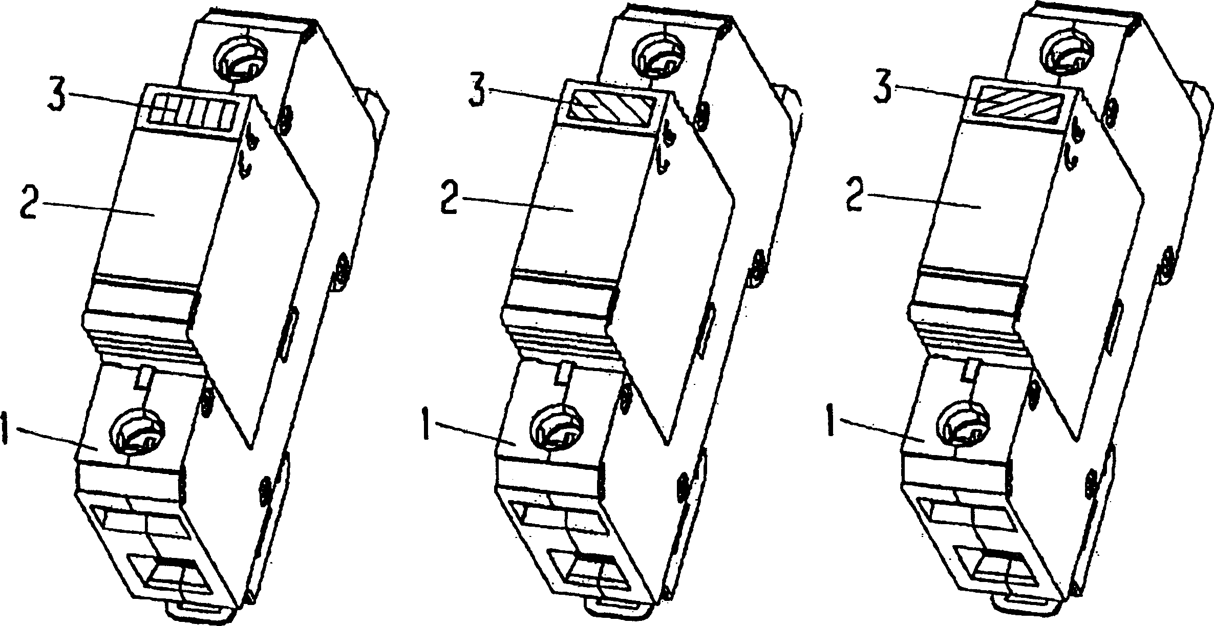
[0029] The correspondingly shown surge arrester comprises a rail-mountable base part 1 with electrical connections arranged on the front side and means for snap-in rail mounting provided on the underside.

[0030] The base part 1 houses an insert part 2 comprising at least one (but preferably two) safety elements (not shown) and a fault detection unit.

[0031] The fault detection unit is operatively connected to a defect display. The defect indicator is configured as a window 3 in the housing of the insert part 2, connected to an optical display element located below the window.

[0032] If the surge arrester including the safety element arranged in the plug-in part is fully functional, a green indication preferably appears in the window 3 of the housing of the plug-in part 2 (as shown on the left in the figure).

[0033] If multiple overvoltages have occurred up to the load range of the safety element, or if one of several safety elements has collapsed, a color change occur...


PUM


Abstract

An over-voltage disconnection device comprises a base (1), insert comprising protection and fault-recognition elements (2) and a window (3) displaying different colors according to the condition of the fault-recognition element namely thermal overload of the protection element or total disconnection.

Description

technical field [0001] According to the preamble of claim 1, the invention relates to a surge arrester comprising a rail-mountable base part with electrical connections and a fault detection device with at least one safety element and operative connection to a defect display A replaceable insert for a unit, the defect indicator includes a window and an optical display element within a housing of the insert. Background technique [0002] A surge arrester especially configured as a telecommunications line protection device is already known from EP0845843B1. This known protective device includes a fault indicator capable of showing that the load limit has been exceeded, even in the event of other electrical faults in the monitored system. For this purpose, the varistor as a surge arrester is contacted via a tensioned elastic reed, where a safety film made of thermoplastic is provided, which keeps the elastic reed taut and prevents the varistor as soon as the varistor reaches a...

Claims


Application Information

Patent Timeline
Patent Type & Authority Applications(China)
IPC IPC(8): H02H1/00H01Q1/38H01Q7/00H01T1/12H01T1/14H02H3/04H02H7/24H02H9/04H04B1/40
CPCH01T1/12H01T1/14
Inventor 彼得·扎赫曼
Owner DEHN SOHNE GMBH CO KG
Learn More