Electronic ballast and correspondent adjustment method

An electronic ballast, DC current technology, applied in electric light sources, electrical components, lighting devices, etc., can solve problems such as instability

Inactive Publication Date: 2006-11-22
PATENT TREUHAND GESELLSCHAFT FUR ELECTRIC GLUEHLAMPEN MBH
View PDF2 Cites 2 Cited by
  • Summary
  • Abstract
  • Description
  • Claims
  • Application Information

AI Technical Summary

Problems solved by technology

As a result, however, it has been necessary to admit that fluorescent lamps with relatively large diameters tend to produce streaked discharges, whereas fluorescent l

Method used


Image

  • Electronic ballast and correspondent adjustment method

Examples


Embodiment Construction

[0015] The exemplary embodiment described in more detail below is a preferred embodiment of the invention.

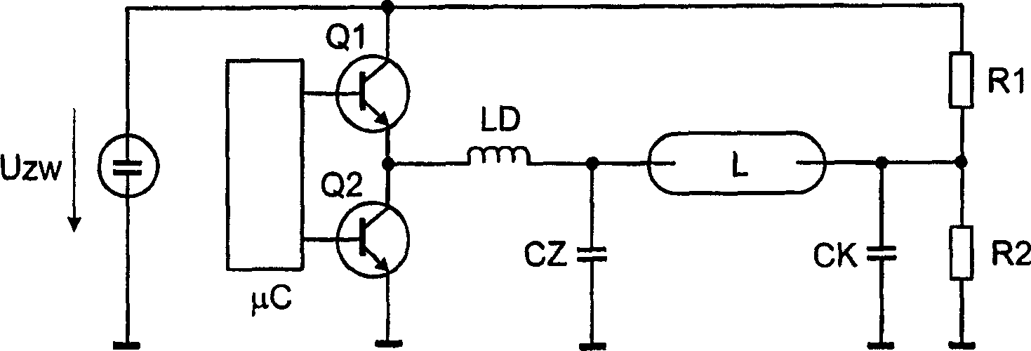
[0016] according to figure 1 In the circuit diagram shown, a fluorescent lamp L is supplied with a DC current via a voltage divider R1 / R2, which reacts in a suitable ratio to the DC intermediate circuit voltage U ZW Divide the voltage, and output the divided voltage at the tap of the voltage divider. One pole of the fluorescent lamp L is connected to the tap. In addition, capacitor CK is connected in parallel with resistor R2 in the voltage divider to ground.

[0017] The DC intermediate circuit voltage U ZW Also as the input voltage of the inverter, which in this example is implemented as a half-bridge comprising a series circuit with two transistors Q1 and Q2. Transistors Q1 and Q2 are controlled by the microcontroller μC at the desired duty cycle.

[0018] A light sensor LD is connected to a node between transistors Q1 and Q2. The other side of the lamp inducto...


PUM


Abstract

An electronic cut-in unit for operating a fluorescent lamp comprises a half-bridge inverter (Q1,Q2), a voltage divider (R1,R2) in parallel to the inverter input with the lamp (L) between the inverter output and the divider. The touch ratio of the inverter can be altered so that a direct current can be passed to the lamp at a desired level. An independent claim is also included for an operating process for the above unit.

Description

technical field [0001] The invention relates to an electronic ballast for starting and / or dimming a fluorescent lamp, said electronic ballast comprising an inverter and a voltage divider connected in parallel with the input of the inverter, thereby having It is possible to have fluorescent lamps connected between the taps of the voltage divider and the output of the inverter. Furthermore, the invention relates to a corresponding method for regulating an electronic ballast for supplying a fluorescent lamp with an alternating current from an inverter and a direct current generated by a voltage divider. Background technique [0002] Dimmable fluorescent lamps can produce streaked discharges under certain conditions. These striated discharges exist as alternating bright and dark regions in a lamp a few centimeters in size. The streaked discharge can be eliminated by sending a low direct current through the lamp in addition to the high frequency alternating current. A circuit ...

Claims


Application Information

Patent Timeline
IPC IPC(8): H05B41/295
CPCH05B41/2858H05B41/2928
Inventor J·克利尔
Owner PATENT TREUHAND GESELLSCHAFT FUR ELECTRIC GLUEHLAMPEN MBH
Why Eureka
Try Eureka