A method of constructing a semi-submersible vessel using dry dock mating

A semi-submersible, dry-dock technology, used in dry-dock, ship construction, hull, etc., to solve problems such as high-risk connection operations, harsh sea conditions, and uncontrollable conditions

Active Publication Date: 2006-11-22
JURONG SHIPYARD
View PDF5 Cites 3 Cited by
  • Summary
  • Abstract
  • Description
  • Claims
  • Application Information

AI Technical Summary

Problems solved by technology

The main disadvantage of this method is that the connection operation is usually very risky, the sea environment is harsh and uncontrollable
Moreover, such operations may face a large number of uncertainties

Method used


Image

  • A method of constructing a semi-submersible vessel using dry dock mating
  • A method of constructing a semi-submersible vessel using dry dock mating
  • A method of constructing a semi-submersible vessel using dry dock mating

Examples


Embodiment Construction

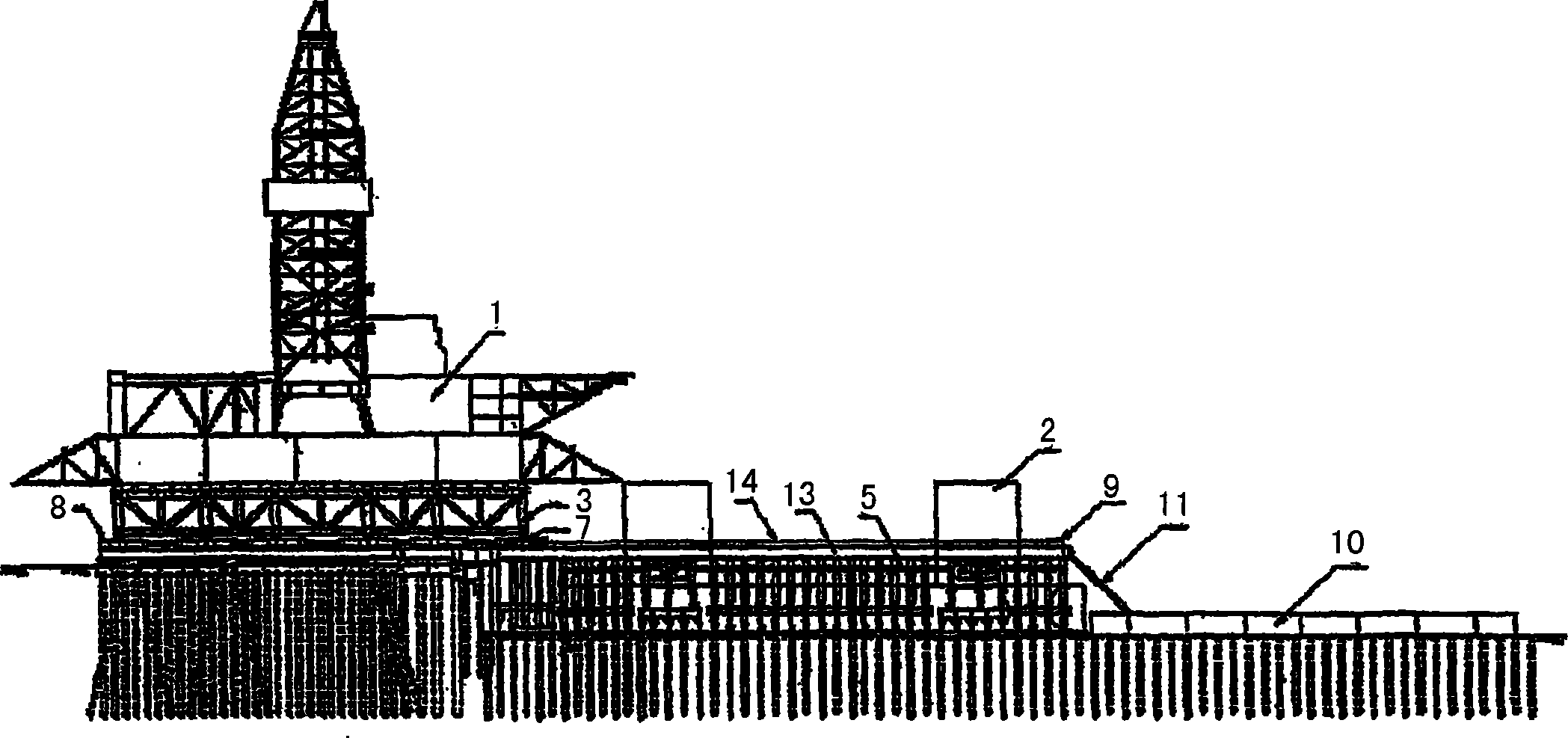
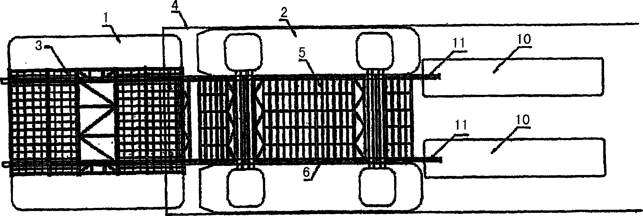
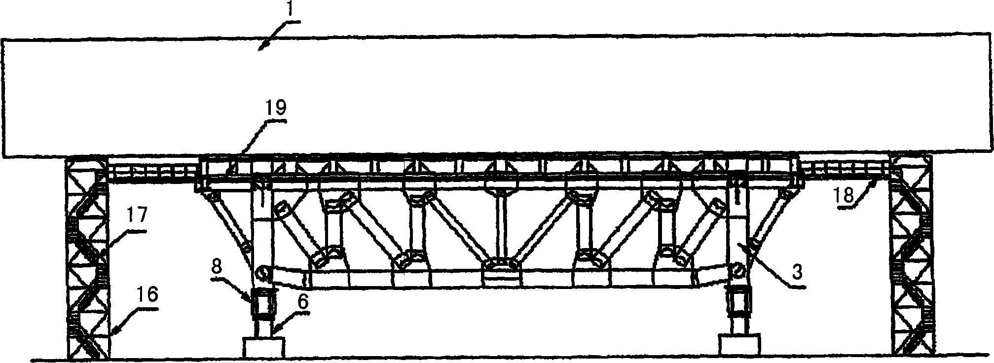
[0024] Now describe in more detail in conjunction with accompanying drawings, figure 1 and figure 2 A general setup of a dock is shown, including a dry dock, in which a semi-submersible drilling rig according to the invention has been built and engaged. Such as figure 1 and figure 2 As shown, the semi-submersible drilling equipment includes an upper shell 1 and a lower shell 2 . During construction, the upper hull 1 is supported by sliding trusses 3 located on the shore adjacent to the dry dock 4 . The truss 3 is also designed to be able to slide the entire upper shell on the sliding beam 6 using the sliding shoes 8 during unloading operations. The auxiliary support structure 5 or support truss 5 is erected in the dry dock 4 .

[0025] Sliding beams or connecting members 6 extend between the support truss 5 and the bottom of the sliding truss 3 . The connecting members 6 are removed from the support trusses after the joining operation is complete, as will be described ...


PUM


Abstract

A method of constructing a semi-submersible drilling rig in a shipyard and fully assembling it in a shipyard. The upper hull (1) is built on land adjacent to the dry dock in which the lower hull (2) is built and the joining of the upper and lower hulls is finally done in the dry dock. The upper shell slides to a position above the lower shell, and the lower shell is floated up by injecting water into the dry dock, and the position of the lower shell is adjusted through the ballast tank in the lower shell. Once the upper and lower hulls are in contact alignment, they are permanently welded together, completing the rig assembly in dry dock.

Description

technical field [0001] The present invention relates generally to a method of building an off-shore structure, and in particular to a method of building a semi-submersible drilling rig, vessel or structure (referred to as a "drilling rig") in a dock. Background technique [0002] There is an increasing demand in the market for semi-submersible drilling equipment capable of oil and gas exploration at depths of more than 150 meters. [0003] There are currently two conventional methods of constructing semi-submersible drilling rigs. The first, the so-called "sequential block build-up" method, provides a method of sequentially building semi-submersible rigs "from bottom to top". According to this method, the lower shell of the platform is floating, and the pillars and connecting supports are first erected piece by piece using a shore crane or a floating crane on water. The upper housing which then stands on the lower housing is assembled in the same way. A major disadvantage...

Claims


Application Information

Patent Timeline
Patent Type & Authority Applications(China)
IPC IPC(8): B63B9/06B63B1/10B63B35/44B63C5/02
CPCB63B1/107B63C5/02B63C2005/022B63B75/00B63B77/00B63B35/44
Inventor 萧丹枫吴金桂钟岿沈士林
Owner JURONG SHIPYARD
Why Eureka
Try Eureka