Ventilation device for laneway grubbing with roadheader

A technology for roadheaders and equipment, applied in the field of ventilation equipment, can solve the problems of inability to reliably eliminate dust explosions, difficulty, and dust-laden airflow that cannot sufficiently pass through the return air duct to remove dust.

Inactive Publication Date: 2006-11-29
CFT GMBH
View PDF0 Cites 5 Cited by
  • Summary
  • Abstract
  • Description
  • Claims
  • Application Information

AI Technical Summary

Problems solved by technology

Significant difficulties exist in this case since the air flow from the fresh air intake duct so swirls the dust and has such an effect that the dust laden air flow cannot pass through the return air duct sufficiently to

Method used


Image

  • Ventilation device for laneway grubbing with roadheader
  • Ventilation device for laneway grubbing with roadheader
  • Ventilation device for laneway grubbing with roadheader

Examples


Embodiment Construction

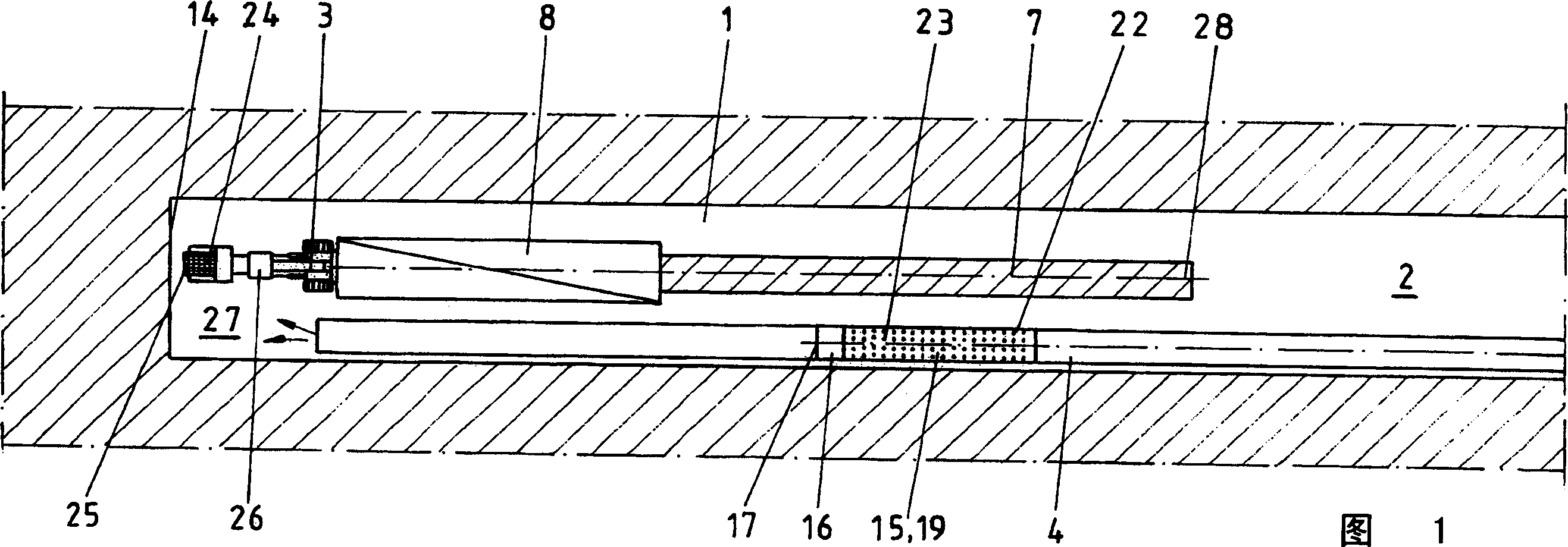
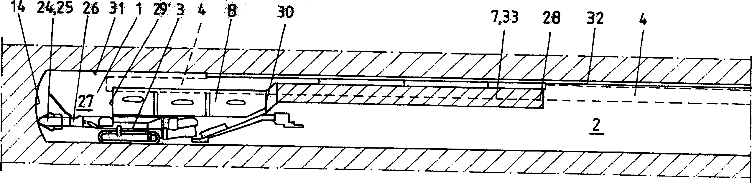
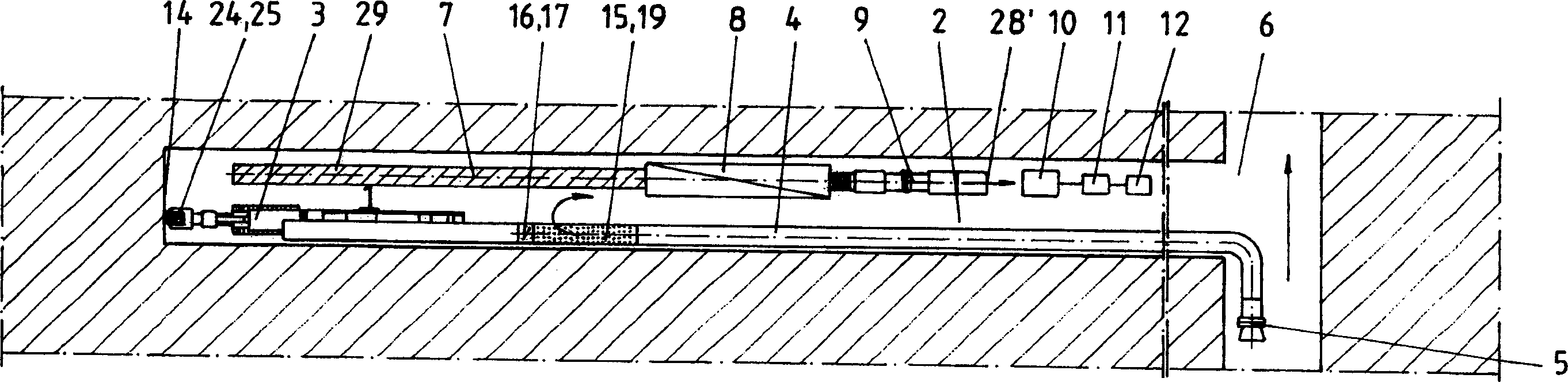
[0022]Fig. 1 shows a top view of a roadway excavation 1 in which, for example, the roadway is dug in the rock. The rock is cut by a roadheader 3, in which a fresh air inlet pipe 4 with a ventilator 5 and a return air pipe 7 with a dust removal device 8 are used for ventilation. The fresh air is sucked from the fresh air lane 6, such as image 3 Shown. For this reason, the ventilator 5 is arranged in the fresh air tunnel 6 and is used to always send a corresponding amount of fresh air through the fresh air inlet pipe 4 to the position of the front wall 14 of the work.

[0023] press image 3 It is shown that only the suction pipe 29 of the suction joint or the dust removal device 8 is provided in the part of the roadheader 3, and the dust removal device 8 itself is arranged far back in the tunnel 2. After the dust removal device 8 is provided a fan station 9, an end 28 of the return air pipe 7, a compressor 10, a compressed air container 11 and a general distribution box 12.

[002...


PUM

PropertyMeasurementUnit
Lengthaaaaaaaaaa

Abstract

A device used for ventilation during roadway excavation (1), wherein the roadheader (3) has a fresh air inlet duct (4) with a secondary discharge device (15) connected in the middle and a dust removal device (8) return air pipe (7). The secondary discharge device (15) is used to form a dust protection wall (20), which is slowly drawn towards the front wall (14) of the working face and is used to divert the dust-laden airflow from the dust area (27) without adverse In the case of turbulence or other influences, it can be reliably introduced into the return air duct (7) or directly into the dust removal device (8) and cleaned there.

Description

Technical field [0001] The invention relates to a ventilation device used for tunnel excavation using a roadheader in underground mining and tunnel engineering. It is equipped with a fresh air inlet pipe and a return air pipe integrated with a dust removal device, wherein the end of the fresh air inlet pipe Hang in a distance no more than 5m away from the wall in front of the work. Background technique [0002] In underground mining and tunnel engineering, in order to ventilate roadways and other working areas, connect these roadways and working areas with fresh air shafts and return air shafts, so that necessary fresh air can pass through the fresh air shafts through the corresponding underground areas Flow to the return air shaft. When digging a new roadway, fresh air must be introduced artificially into the driving roadway from a roadway communicating with the air intake shaft and the return air shaft. For this, use a fresh air inlet duct and a return duct if necessary. The fr...

Claims


Application Information

Patent Timeline
IPC IPC(8): E21C35/22E21D9/00
Inventor R·博特
Owner CFT GMBH
Why Eureka
Try Eureka