Heat storage apparatus
A heat storage device and heat storage technology, which is applied in heat storage equipment, heat storage heat exchangers, heating fuels, etc., can solve the problems of low efficiency and low utilization rate of heat storage agent, and achieve the effect of improving utilization rate
- Summary
- Abstract
- Description
- Claims
- Application Information
AI Technical Summary
Problems solved by technology
Method used
Image


Examples
Embodiment 1
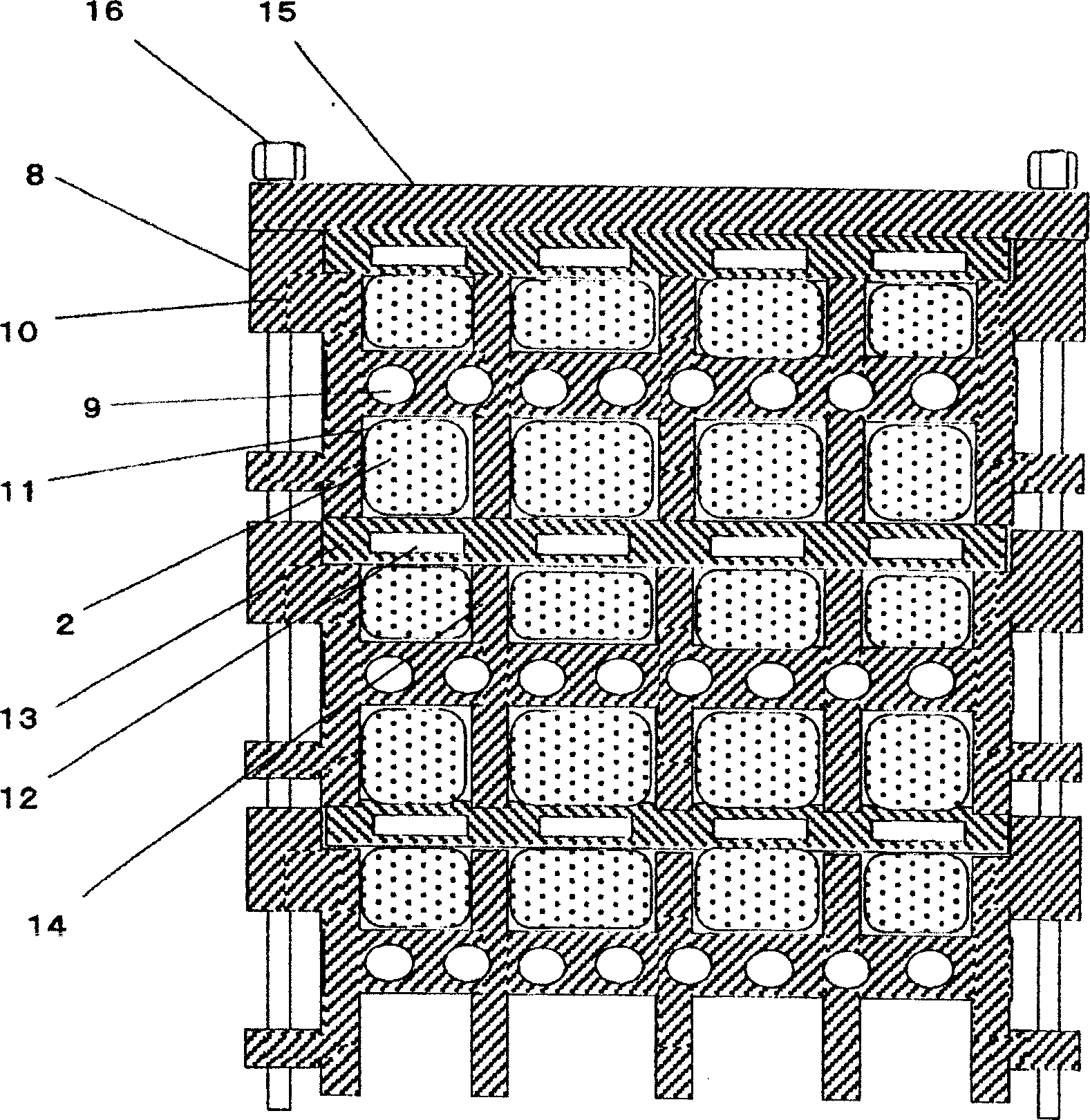
[0031] figure 1 It is a structural schematic diagram of the heat storage device in the first embodiment of the present invention.
[0032] Such as figure 1 As mentioned in , the heat storage component 8 is composed of a profile 10 with a primary fluid flow path 9 , and one side or both sides of the profile 10 is provided with a heat storage body 11 , and the heat storage body 11 contains a heat storage agent 2 . The flow path plate 13 has the secondary fluid flow path 12 and is clamped by the raised portion 14, and the profiles 10 and the flow path plate 13 are stacked in sequence. The heat accumulator 11 is arranged to be in close contact with the heat accumulator component 8 and the flow path plate 13 , and an end plate 15 is provided on the outermost side thereof, and the end plate 15 is fastened by fasteners 16 such as screws.
[0033] The operation and function of the thermal storage device having the above-mentioned configuration will be described below.
[0034] Fi...
Embodiment 2
[0037] figure 2 It is a schematic structural view of the heat storage device in the second embodiment of the present invention.
[0038] exist figure 2 Among them, the profile 10 in the heat storage component 8 is made of aluminum extruded profile, and the outer surface of which is in contact with the heat storage body 11 composed of a heat storage agent 2 such as sodium acetate trihydrate is provided with a resin or the like. Anti-corrosion surface film17.
[0039]The working conditions and functions of the thermal storage device with the above-mentioned configuration will be described below.
[0040] Firstly, although the regenerator 11 made of regenerator 2 such as sodium acetate trihydrate will be in contact with both sides of the aluminum extruded profile 10, since there are anti-corrosion coatings 17 on both sides of the profile 10, It can prevent the heat storage agent 2 from directly contacting with aluminum, and prevent aluminum ions from dissolving into the heat...
Embodiment 3
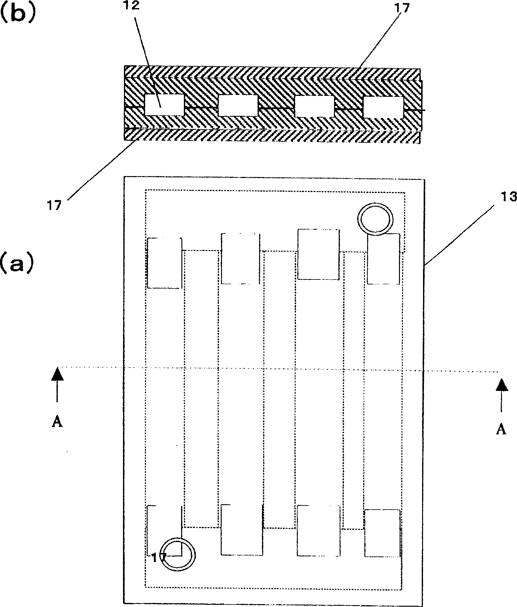
[0043] image 3 It is a schematic structural view of the heat storage device in the third embodiment of the present invention.
[0044] exist image 3 Among them, the flow path plate 13 is made of copper plate, and the outer surface in contact with the profile 10 and the heat storage agent 2 is provided with an anti-corrosion film 17 by means of chrome plating or the like.
[0045] The working conditions and functions of the thermal storage device with the above-mentioned configuration will be described below.
[0046] When the heat storage component 8 and the flow path plate 13 are laminated, the surface of the flow path plate 13 contacts the heat storage agent 2 and the raised portion 14 of the profile 10 . Since the flow path plate 13 is made of copper plate with excellent thermal conductivity, heat can be well transferred from the heat storage agent 2 to the secondary fluid. Moreover, since the anti-corrosion film 17 is provided on the surface of the flow path plate 13,...
PUM
 Abstract
Description
Claims
Application Information
 - R&D Engineer
- R&D Manager
- IP Professional
- Industry Leading Data Capabilities
- Powerful AI technology
- Patent DNA Extraction
Browse by: Latest US Patents, China's latest patents, Technical Efficacy Thesaurus, Application Domain, Technology Topic.
© 2024 PatSnap. All rights reserved.Legal|Privacy policy|Modern Slavery Act Transparency Statement|Sitemap