Protective boot for universal joint

A bellows and matrix technology, applied in the field of bellows, can solve the problem that the bellows cannot satisfactorily solve the load moment and the like, and achieve the effects of improving axial rigidity and resistance torque.

Inactive Publication Date: 2006-12-06
CARL FREUDENBERG KG
View PDF0 Cites 5 Cited by
  • Summary
  • Abstract
  • Description
  • Claims
  • Application Information

AI Technical Summary

Problems solved by technology

[0003] Bellows are known not to satisfactorily resolve such load moments

Method used


Image

  • Protective boot for universal joint
  • Protective boot for universal joint
  • Protective boot for universal joint

Examples


Embodiment Construction

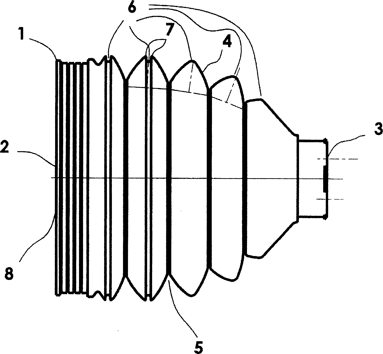
[0038] figure 1 Represents a bellows having a base body 1 with a first end 2 and a second end 3, wherein the ends 2, 3 are movable relative to each other, forming a plurality of circumferential The arches 4 are spaced apart from each other by first indentations 5 and a second indentation 6 is formed on at least one of the arches 4 . In this case, the width of the second undercut 6 has a value at most corresponding to the value of its depth. The second constriction 6 is surrounded by two ribs 7 . The first indentation 5 and the second indentation 6 are arranged concentrically to the axis passing through the ends 2 , 3 . The second indentation 6 is formed in the outermost peripheral region of the dome 4 .

[0039] The base body 1 is designed to be rotationally symmetrical. The ends 2 , 3 are designed as ends 2 , 3 of an axial through-hole 8 on the base body 1 . The base body 1 is designed at least partially in the shape of a truncated cone.

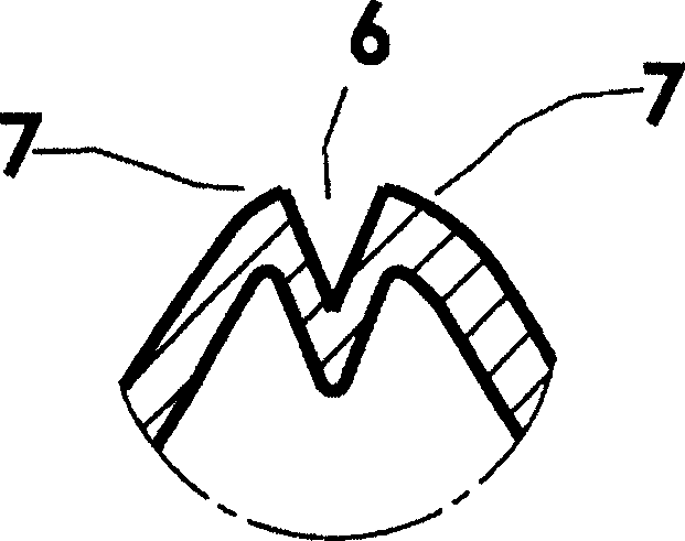
[0040] figure 2 Indicates a ...


PUM


Abstract

A bellows having a substructure including a first end and a second end, the ends being movable relative to one another, circumferential bulges, which are spaced apart by first constricted regions, being formed in the substructure between the ends, and a second constricted region being formed in at least one bulge. The width of the second constricted region corresponds at least to its height in order to reduce the axial stiffness and increase the radial stiffness.

Description

technical field [0001] The invention relates to a bellows comprising a base body with a first end and a second end, wherein the two ends are movable relative to each other and wherein a circumferential arch is formed between the inner ends of the base, They are separated from each other by a first indentation, and a second indentation is formed in at least one of the domes. Background technique [0002] Bellows of this type are known from the prior art, and DE 25 05 542 A1 discloses a bellow of this type, the second constriction of which is very shallow and wide. Bellows of this type are often fitted on joints, especially on joints / universal joints of automotive drive shafts. Bellows can bear loads both axially and radially. During operation, the corrugations of such a bellows are stretched on one side and compressed on the other side during deflection or bending of the joint, whereby high compressive stresses occur in the outer region belonging to the corrugation tip. Th...

Claims


Application Information

Patent Timeline
Patent Type & Authority Applications(China)
IPC IPC(8): F16J3/04
CPCF16J3/043
Inventor S·席尔默
Owner CARL FREUDENBERG KG
Why Eureka
Try Eureka