
Injection units for molding machines

A technology of injection unit and molding machine, applied in ceramic molding machines, manufacturing tools, etc., can solve problems such as difficulty in adjustment

Inactive Publication Date: 2017-07-28
ENGEL AUSTRIA
View PDF6 Cites 0 Cited by
  • Summary
  • Abstract
  • Description
  • Claims
  • Application Information

AI Technical Summary

Problems solved by technology

[0003] Incompressible molded masses (e.g. plastics depending on additives) create difficulties in adjustment compared to generally strongly compressible molded masses (most plastics)

Method used


Image

  • Injection units for molding machines
  • Injection units for molding machines
  • Injection units for molding machines

Examples


Embodiment Construction

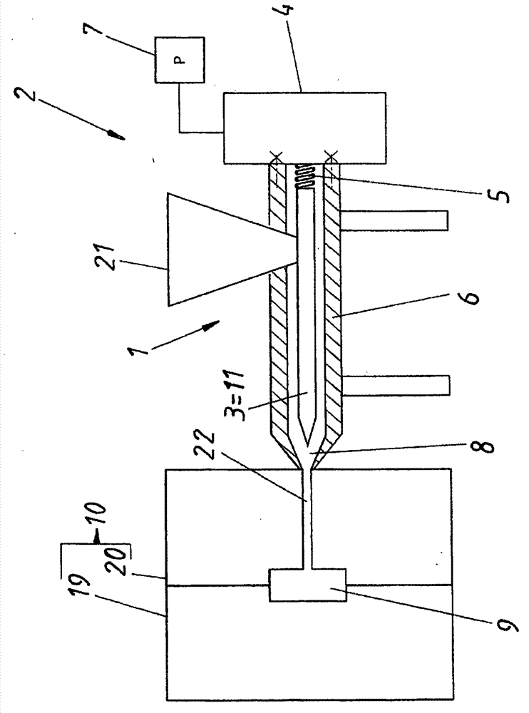
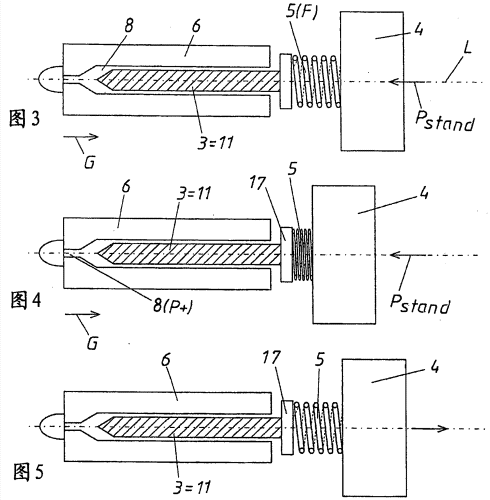
[0024] figure 1 A molding machine 2 is shown schematically, which has an injection unit 1 and a molding tool 10 as essential components. Furthermore, such a molding machine 2 normally also includes a mold clamping plate and a crank mechanism, not shown. To form molded parts or injection molded parts, the raw material (such as plastic granules, metal or ceramic powder, additional fillers such as glass fibers, additional liquids or mixtures if necessary) is first introduced via the injection funnel 21 into the In the intermediate chamber between cylinder 6 and injection piston 3. If the injection piston 3 is designed as an injection worm 11 , the raw material is melted by rotating the injection worm 11 . A rotational movement is introduced into the injection worm 11 by means of the drive 4 . Injection takes place after melting is complete, for which the drive 4 moves the injection worm 11 pistonically or in translation, so that the accumulated molten injection material 8 is i...


PUM


Abstract

An injection assembly (1) for a molding machine (2), in particular an injection molding machine, comprising an injection piston (3), a drive device (4) for moving the injection piston (3), and a force storage means, wherein the force storage means connects the drive device (4) to the injection piston (3).

Description

technical field [0001] The invention relates to an injection unit for a molding machine, in particular an injection molding machine, having an injection piston, a drive for moving the injection piston and an energy store. Furthermore, the invention relates to a molding machine having at least one such injection unit. Background technique [0002] Injection units for molding machines have undergone many developments in recent years. In this case, it is especially important that the molded parts produced are produced with ever-greater quality and reproducibility and with ever-increasing precision. Important areas to be observed here are all injection areas or injection channels and here in particular the injection pressure which has a significant effect on the quality of the molded part. In recent years, in addition to pure plastics, additives such as metals, glass fibers etc. have been increasingly used in molding and injection molding processes. Especially in the case of ...

Claims


Application Information

Patent Timeline
Patent Type & Authority Patents(China)
IPC IPC(8): B29C45/52B29C45/84B22F3/22B28B1/24
CPCB29C45/531B29C45/5008B29C45/77
Inventor F·迪尔奈德G·哈格尔M·古森鲍尔H·伯恩哈德
Owner ENGEL AUSTRIA
Learn More