Flywheel for internal combustion engine

A technology of internal combustion engine and inertial flywheel, applied in the field of inertial flywheel, can solve the problems of increasing complexity and large size

Active Publication Date: 2008-01-02
VALEO EMBRAYAGES SAS
View PDF1 Cites 3 Cited by
  • Summary
  • Abstract
  • Description
  • Claims
  • Application Information

AI Technical Summary

Problems solved by technology

Assembly of these weights manifests itself in larger size and increased complexity

Method used


Image

  • Flywheel for internal combustion engine
  • Flywheel for internal combustion engine
  • Flywheel for internal combustion engine

Examples


Embodiment Construction

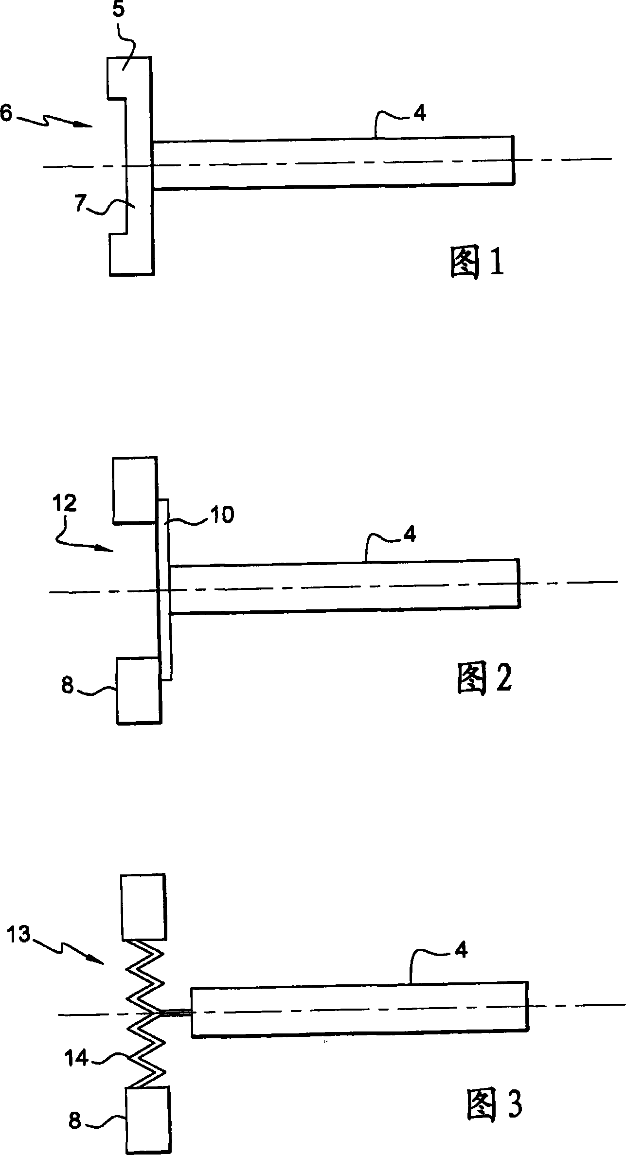
[0035] [34] The schematic diagram in FIG. 1 shows a rigid inertial flywheel 6 which is generally made of cast iron and is fastened to the crankshaft 4 of an internal combustion engine, in particular a motor vehicle internal combustion engine. The flywheel generally comprises a radially outer portion 5 of greater thickness, which imparts a high inertia, and a coupling part 7 between the radially outer portion 5 and the crankshaft 4 . The coupling part 7 is fastened to one end of the crankshaft 4 by means of screws, not shown, arranged along a pair of circles centered on the shaft.

[0036] [35] The schematic diagram of FIG. 2 shows a curved flexible inertial flywheel 12 comprising a ring 8 usually made of cast iron fixed to the outer periphery of an annular plate 10 . Said plate 10, screwed to the crankshaft 4, makes the flywheel 12 flexible, allowing bending about an axis, which is perpendicular to the axis of the crankshaft, and exhibiting a surge movement (mouvement de pomp...


PUM


Abstract

The invention relates to a flywheel (1) for an internal combustion engine comprising a rotating annular flywheel mass (22) which is fixed to one end of the engine crankshaft (4) by a connecting means (14) having a torsional stiffness of less than that of the crankshaft (4) alone, such that the natural torsional frequency of the crankshaft (4) fixed to the flywheel (1) is reduced, but still greater than the first frequency generated by successive combustion events in the cylinders of the engine.

Description

technical field [0001] [01] The present invention relates to an inertial flywheel for an internal combustion engine, in particular a motor vehicle internal combustion engine. Background technique [0002] [02] It is known to use a rigid flywheel, which has a high rotational inertia and is fixed at one end of the crankshaft between the crankshaft and a transmission, in order to drive the wheels, especially of motor vehicles. The purpose of this rigid flywheel is to regulate the rotational speed of the crankshaft. Combustion in the engine cylinders produces a series of momentary torque peaks that the inertial flywheel converts into a substantially vibration-reduced average torque to reduce vibration. [0003] [03] The inertia flywheel forms a mass body (masse) fixed on the crankshaft, so that the crankshaft-flywheel assembly forms a mass body-spring system with a natural frequency of vibration, wherein the crankshaft has a certain resistance to longitudinal bending stiffness...

Claims


Application Information

Patent Timeline
Patent Type & Authority Applications(China)
IPC IPC(8): F16F15/121F16D3/79
CPCF16F15/3153F16F15/1315
Inventor R·韦霍格H·马埃
Owner VALEO EMBRAYAGES SAS
Why Eureka
Try Eureka