Catenary constant tension pay-off car

A technology of constant tension and pay-off car, which is applied in the direction of overhead lines, thin material handling, and delivery of filamentous materials, etc. It can solve the problems of inability to monitor and adjust, too fast pay-off, and high production costs, so as to reduce exhaust gas emissions , Realize the effect of automatic adjustment and reduce maintenance cost

Pending Publication Date: 2020-08-14
CHINA CREC RAILWAY ELECTRIFICATION BUREAU GRP
View PDF0 Cites 2 Cited by
  • Summary
  • Abstract
  • Description
  • Claims
  • Application Information

AI Technical Summary

Problems solved by technology

[0004] 1. In the prior art, the carrying wire enters the tension applying device after coming out of the winding device. Because the winding device and the tension applying device are fixed on the road flat car and cannot be moved, and the winding device is wide, the two edges have A certain distance, so when unwinding, the carrying wire at the two edges of the winding device cannot be aligned with the tension applying device, and after the carrying wire is released, the carrying wire between the winding device and the tension applying device will have a certain inclination Angle, the carrying wire cannot enter the tension applying device vertically, causing serious friction between the carrying wires, reducing the quality of the carrying wire, and causing a safety hazard;
[0005] 2. Before the winding device in the prior art enters the tension applying device, there is no other resistance except the resistance of its own weight when the rotating shaft rotates, so it only relies on the pulling force generated by the tension applying device to rotate. When the upper bearing wire is released, the weight will gradually decrease, and the rotation resistance of the winding device itself will become smaller and smaller, which will cause excessive rotation and excessive wire release, so that the tension of the bearing wire between the winding device and the tension applying device will be reduced. The tension value is getting smaller and smaller, which means that the carrying wire wound on the tension applying device is gradually loosened, so that the carrying wire coming out of the tension applying device often touches the ground and the rail due to insufficient tension, which seriously reduces the catenary structure. Stability and elasticity, the prior art usually uses mechanical methods such as sticks or clutches to make the rotating shaft generate resistance when the wire is unwound, but this method can only generate a small tension on the wire, and cannot perform real-time monitoring and adjustment, and the tension of the carrying wire cannot be monitored and adjusted in real time according to the actual situation, and the tension cannot be kept constant;
[0006] 3. The structure of the support in the prior art is complex. When installing the winding device, the entire support needs to be disassembled and installed, which is time-consuming and laborious, and the production cost is relatively high
[0008] The electro-hydraulic control system used on the domestic constant tension pay-off car is not yet mature, the engine power is large, the pollutant discharge is large, the overall volume is large, and various failures are prone to occur during the working process
For example: the main control motor in the hydraulic control assembly generally indirectly drives multiple hydraulic oil pumps through the transfer case, and once the transfer case as the power transmission hub is damaged, the entire vehicle will not be able to work; another one is connected to the hydraulic oil pump The layout of control valves and oil pipes is complicated and messy. After a fault occurs, it is necessary to check the faults one by one before performing corresponding maintenance, which is time-consuming and labor-intensive; If a part is damaged, it needs to be purchased from the original manufacturer, which not only wastes time, but also costs a lot of maintenance

Method used


Image

  • Catenary constant tension pay-off car
  • Catenary constant tension pay-off car
  • Catenary constant tension pay-off car

Examples


Embodiment

[0045] Example Catenary constant tension pay-off car

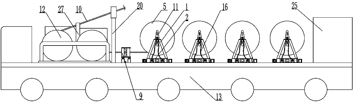
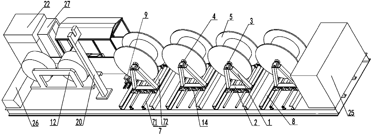
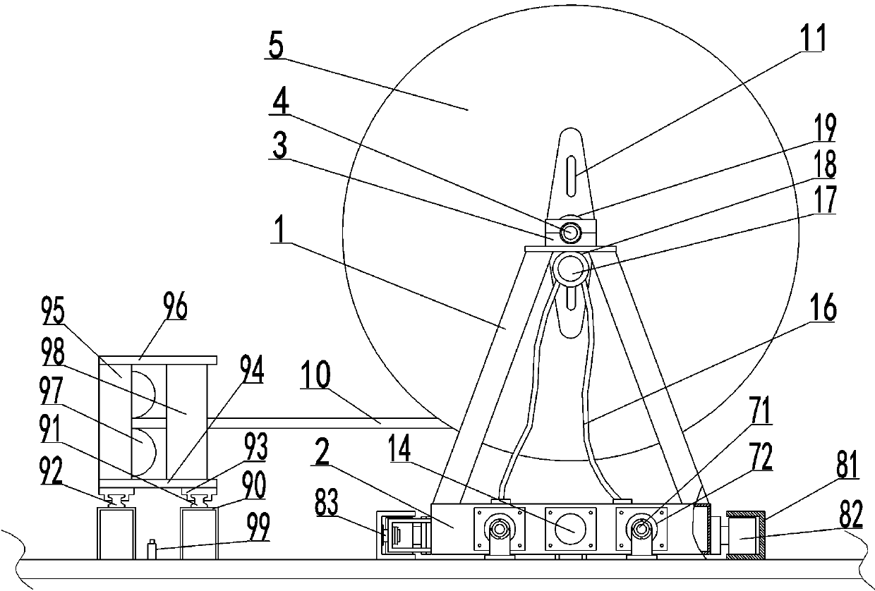
[0046] This example Figure 1-Figure 9 As shown, a catenary constant tension wire pay-off vehicle includes a bracket 1 fixed on a road flat car 13, a rotating shaft 4 connected to the bracket 1 in rotation, and a coil fixed on the rotating shaft 4 for winding the bearing wire 10. The wire device 5, the support 1 is composed of two trapezoidal structures arranged in parallel, the upper part is narrow and the lower part is wider, and the lower part is connected together by a welded base 2. The top of the bracket 1 is detachably provided with two bearing seats 3, the bearing seats 3 are respectively arranged on two parallel trapezoidal structures of the bracket 1, and the rotating shaft 4 is connected to the bearing seats 3 through bearing rotation, The two ends of the rotating shaft 4 are respectively arranged on the two bearing seats 3 . The bearing seat 3 is composed of upper and lower parts, which are fastened to each o...


PUM


Abstract

The invention discloses a catenary constant tension pay-off car, comprising a pay-off device fixedly arranged on a road flat car and penetrated through bearing wires in sequence, a guiding device, a tension applying device, a wire column and a control device. A slide rail device and a hydraulic cylinder for moving a bracket along the slide rail device are fixedly arranged on the road flat car. A hydraulic motor is fixedly arranged on the bracket, and the direction of force applying when the hydraulic motor provides tension for a winding device is opposite to the direction of paying-off of thewinding device. The control device comprises a generator set and a hydraulic control assembly; the hydraulic control assembly comprises a signal control assembly and an oil storage device, a hydraulicoil pump and an integrated valve group connected in sequence. The pay-off car has a high degree of automation, the modularization is achieved, the size is small, constant tension is ensured, and thetension is automatically adjusted according to actual conditions during the working process. In addition, the quality of winding is ensured, the service life is long, the disassembly and assembly areconvenient, the orientation is stable, the energy is saved, the emission is reduced, the environmental pollution is low, and the pay-off car is suitable for all catenary pay-off cars.

Description

technical field [0001] The invention belongs to the technical field of railway bearing and erection, and relates to a catenary wire pay-off car, in particular to a catenary constant tension wire pay-off car. Background technique [0002] During the construction or maintenance of electrified railways, the tension of the catenary wires plays an extremely important role in maintaining the spatial form of the catenary. The bearing wire is the contact wire and catenary cable erected on the railway line. During construction, the bearing wire needs to be erected on the wrist arm of the catenary pole and maintain a certain tension. When erecting the carrying wire, the construction is carried out by catenary operation vehicles. Since the carrying wire needs to be wound on the pay-off frame before erection, the carrying wire will become curved and produce radians, and the existence of the radian of the carrying wire itself will cause Make it produce intermittent ripples and form arc ...

Claims


Application Information

Patent Timeline
Patent Type & Authority Applications(China)
IPC IPC(8): B65H59/38B65H49/30B65H49/38B65H59/04B65H63/00B65H59/40B65H57/28B60M1/22B60M1/28
CPCB65H59/381B65H49/30B65H49/38B65H59/04B65H63/00B65H59/40B65H57/28B60M1/28B60M1/22B65H2701/35B65H2701/36B65H49/34B65H49/32B65H59/005
Inventor 刘桐任增堂苗俊波袁英杰陈桀李剑锋张柏滔唐立新高越崔达周辰彦
Owner CHINA CREC RAILWAY ELECTRIFICATION BUREAU GRP
Why Eureka
Try Eureka