Cooling plate
A cooling plate and cooling medium technology, applied in ion implantation plating, lighting and heating equipment, coating, etc., can solve the problems of distance change, backplane strength weakening, bending, etc., and achieve less local deformation and longer replacement life long effect
- Summary
- Abstract
- Description
- Claims
- Application Information
AI Technical Summary
Problems solved by technology
Method used
Image
Examples
no. 1 example
[0034] The structure of the backplane is as follows.
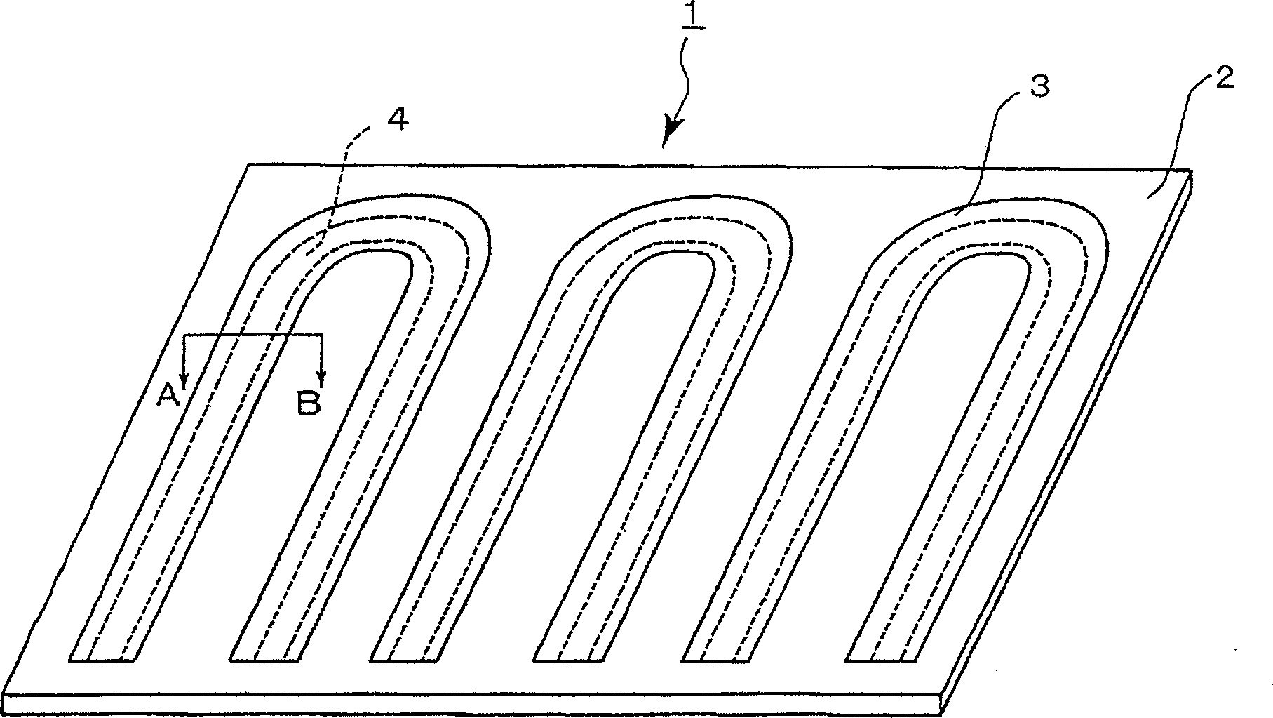
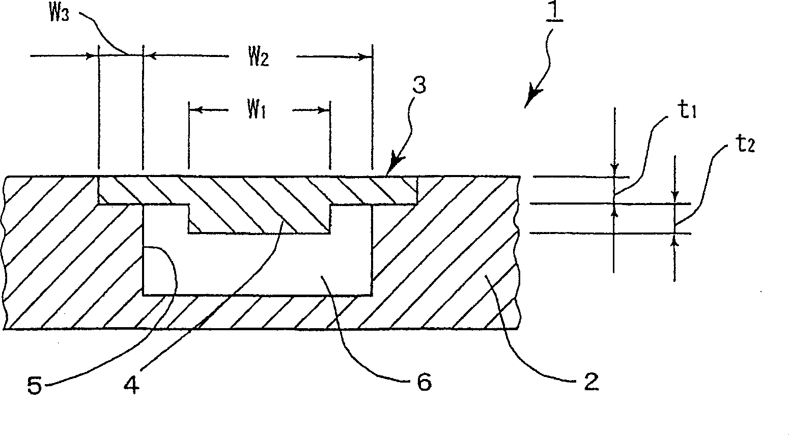
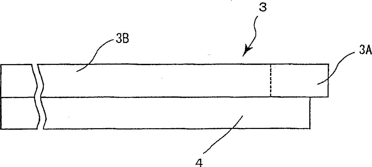
[0035] figure 1 and figure 2 A perspective view and a partial sectional view (along the figure 1 in the A-B line part). image 3 A side view showing a cover constituting the back plate of the first embodiment of the present invention. refer to Figures 1 to 3 , the configuration of the backplane of the first embodiment will be described below.
[0036] The backplane 1 has a main body 2 and a cover 3, and the main body 2 has a width W opened on one side. 2 slot 5. The cover 3 has a width W at its inner side, that is, one side of the groove 5. 1 The convex part (flange) 4. The convex portion 4 is provided continuously along the entire length of the cover 3 (in the length direction) at an approximately central portion thereof. From the standpoint of strength, it is desirable that the width W of the convex portion 4 1 than the width of slot 5 W 2 Small, at W 2 / 4 or more. preferably at W 2 / 3 or more, more pre...
no. 2 example
[0052] Figure 7 is a partial cross-sectional view of a back plate showing a second embodiment of the present invention. Figure 7 The difference between the shown backplane 31 and the backplane 1 of the first embodiment is only that the width W of the protrusion 34 of the cover 33 1 Made with the width W of the groove 35 of the body 32 2 Basically the same build. In this way, the cooling plate 7 of the second embodiment has the strength to withstand higher stress. The description of applicable modification examples and the like is omitted since they are the same as those of the first embodiment.
[0053] The strength against deformation and the moment of inertia of the section under stress (mm 4 ) proportional to. For example, in the second embodiment also applicable Image 6 , let the thickness of the cover (t 1 ) is 3mm, set the cross-section of the water channel as height 5mm×width 100mm, and set the height (thickness t 2 ) 2.5mm x width (runner width direction) 10...
no. 3 example
[0055] Figure 8 is a partial cross-sectional view of a back plate showing a third embodiment of the present invention. Figure 8 The difference between the shown backboard 41 and the backboard 1 of the first embodiment is only that the outer surface of the cover 43 protrudes from the surface on the same side as the above-mentioned outer surface of the body 42, and the cover 43 is connected to the body 42. combined. The description of applicable modification examples and the like is omitted since they are the same as those of the first embodiment.
[0056] This embodiment is not limited to the method of providing the convex part of the back plate on the outside of the cover in the first embodiment and the second embodiment, but also includes the method of making the width of the convex part wider than the width of the groove, or only The method of thickening the thickness of the cover ( Figure 8 ).
[0057] Figure 8 In the shown backplane 41, there is a width W 1 The c...
PUM
 Abstract
Description
Claims
Application Information
 - R&D
- Intellectual Property
- Life Sciences
- Materials
- Tech Scout
- Unparalleled Data Quality
- Higher Quality Content
- 60% Fewer Hallucinations
Browse by: Latest US Patents, China's latest patents, Technical Efficacy Thesaurus, Application Domain, Technology Topic, Popular Technical Reports.
© 2025 PatSnap. All rights reserved.Legal|Privacy policy|Modern Slavery Act Transparency Statement|Sitemap|About US| Contact US: help@patsnap.com


