Cross feed broadband omnidirectional antenna

An omnidirectional antenna, cross-feeding technology, applied in resonant antennas, independent antenna unit combinations, and mid-position feeding between antenna endpoints, etc., can solve the problems of increasing antenna loss, increasing cost, and increasing antenna size, etc. Achieve the effect of improving antenna gain, easy processing, and slowing down changes

Inactive Publication Date: 2006-12-20
BEIHANG UNIV
View PDF0 Cites 9 Cited by
  • Summary
  • Abstract
  • Description
  • Claims
  • Application Information

AI Technical Summary

Problems solved by technology

These technologies often have defects in some aspects or have limited frequency band expansion effects. For example, the use of thick substrates is easy to excite surface waves; the addition of passive patches and the use of multi-layer ...

Method used


Image

  • Cross feed broadband omnidirectional antenna
  • Cross feed broadband omnidirectional antenna
  • Cross feed broadband omnidirectional antenna

Examples


Embodiment Construction

[0024] The present invention will be further described in detail below in conjunction with the accompanying drawings.

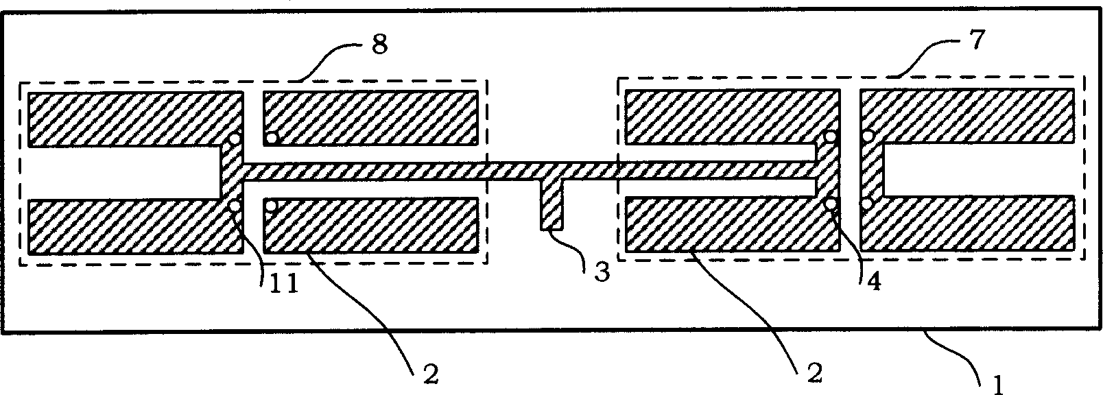
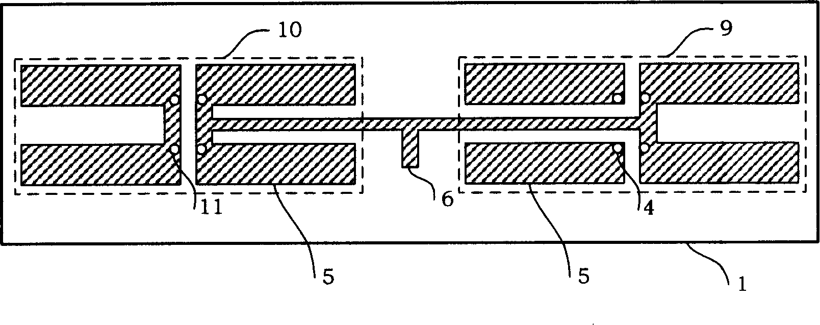
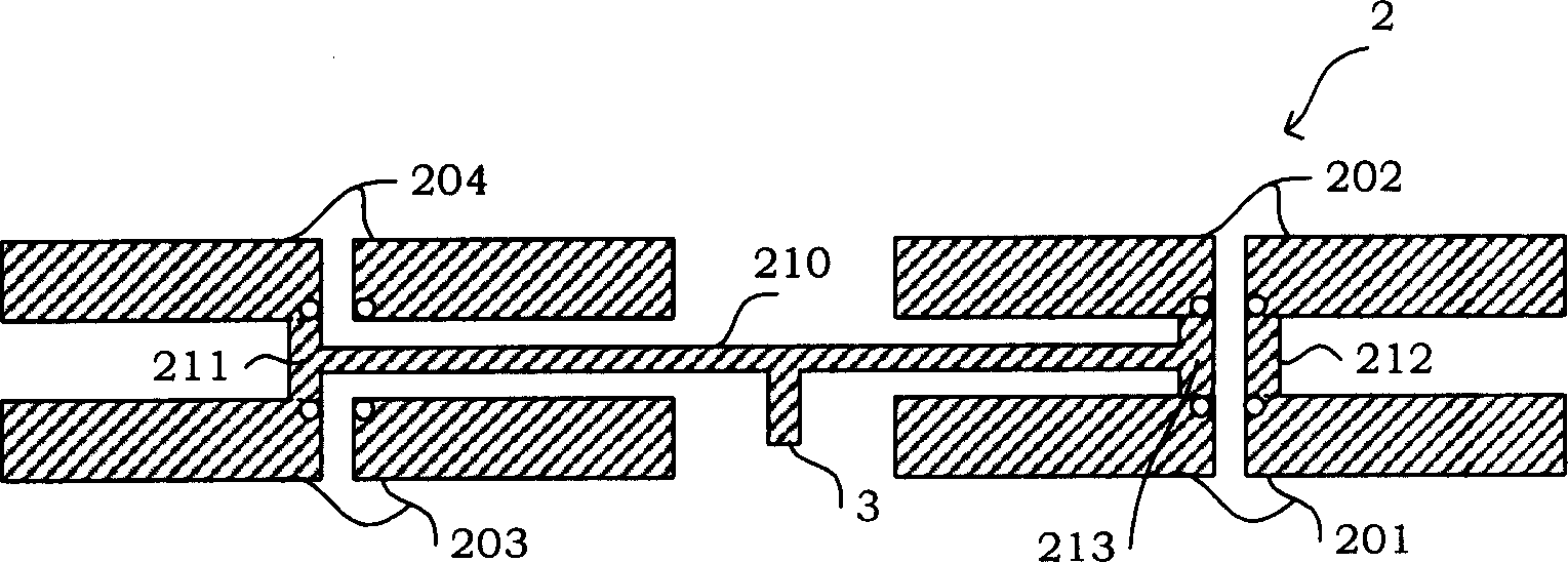
[0025] See Figure 1A , Figure 1B , Figure 2A and Figure 2B As shown, the present invention is a cross-feed broadband omnidirectional antenna. The antenna adopts double-sided copper clad printing on the microwave dielectric board 1 to form an upper antenna unit 2 and a lower antenna unit 5. The upper antenna unit 2 and the lower antenna unit 5 is provided with a metal via hole; the upper layer antenna unit 2 is composed of a connection line 210, a radiation unit A7 and a radiation unit B8; a feed port 3 is provided on the connection line 210; the radiation unit A7 is composed of a wide symmetrical vibrator A201 and a wide symmetrical Composed of oscillator B202, the anti-phase ends of wide symmetrical oscillator A201 and wide symmetrical oscillator B202 are connected in parallel through connector 212, and the non-phase ends of wide symmetrical oscillator...


PUM


Abstract

The invention relates to a cross feed wideband omnidirectional aerial, which uses dual-surface copper print to form upper aerial unit and lower aerial unit on the microwave medium plate, wherein the upper and lower aerial units have metallic through holes; the upper aerial unit is formed by connecting wire, radiation unit A, and radiation unit B; the connecting wire has feed port; the lower aerial unit is formed by connecting wire, radiation unit A, and radiation unit B; the connecting wire has feed port; the radiation units A upper and lower aerial units form the symmetry vibrator aerial radiation device A with load capacitance; the radiation units B of upper and lower aerial units form the symmetry vibrator aerial radiation device B with load capacitance; the connecting wires of upper and lower aerial units form the parallel wide couple dual wires with cross feed electricity to the symmetry vibrator aerial devices (A, B).

Description

technical field [0001] The invention relates to an antenna printed on a dielectric board, more particularly, to a cross-fed broadband omnidirectional antenna with a capacitive load radiation unit. Background technique [0002] Printed antenna has unique advantages such as low profile, easy processing, low cost, and can be integrated with active devices, so it has a wide range of applications and has aroused great interest. The research on printed antennas has developed rapidly and has become an important research direction in the field of antennas. [0003] The common disadvantage of printed antennas is their narrow bandwidth, which limits their application in broadband situations. How to broaden the bandwidth is an important research content. Currently proposed technologies include thickening the substrate or using a thick air medium; using the relative permittivity ε r Substrates with small or large loss tangent tanδ, capacitive feeding (impedance matching); wedge-shaped...

Claims


Application Information

Patent Timeline
IPC IPC(8): H01Q1/38H01Q9/04H01Q9/16H01Q21/30
Inventor 苏东林丁轲佳王冰切欧阳绍修彭飞杨智辉李汉西
Owner BEIHANG UNIV
Why Eureka
Try Eureka