Water drainage pump
A drainage pump and impeller technology, applied to pumps, pump devices, pump components, etc., can solve problems such as insufficient starting force, impact noise, customer dissatisfaction, cracks in the impeller 50 of the rotating shaft head, etc., to minimize damage and minimize noise the effect of
Inactive Publication Date: 2006-12-27
LG ELECTRONICS (TIANJIN) APPLIANCES CO LTD
0 Cites 0 Cited by
AI-Extracted Technical Summary
Problems solved by technology
[0017] However, in the structure of the above-mentioned drain pump according to the prior art, even if the rotation direction of the above-mentioned rotor 30 is changed, the starting force for driving the rotation shaft head 60 of the impeller head 51a is still insufficient, so that the rotation direction of the rotor 30 is reversed. The phenomenon of conversion persistence
[0018] Therefore, there is cont...
Abstract
The invention relates to a discharging pump used in washing machine, wherein the invention improves the driving force transmission structure between blade wheel and rotation axle to drive the blade wheel successfully, and reduce the impact possibility, to reduce noise and avoid hurting fittings. And the invention is formed by: blade wheel whose one part of inner circumference has protruded blade wheel head; frame with blade wheel containing part and rotor containing part; rotation axle formed along the axial center of rotor; and driving force transmitter. Said driving force transmitter is combined with rotation axle; when the rotation axle rotates to reach some starting force, via the circle center force, the rotation axle will be suspended with the blade wheel head to rotate the blade wheel.
Application Domain
Pump componentsOther washing machines +4
Technology Topic
ImpellerEngineering +1
Image
Examples
- Experimental program(1)
Example Embodiment
[0049] Below, will refer to Figure 5 to Figure 9 , the possible embodiments of the drainage pump according to the present invention will be described in more detail.
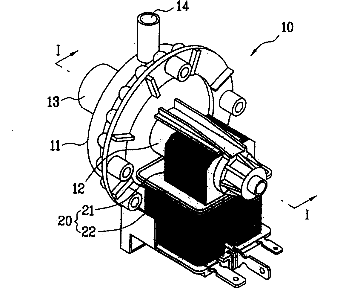
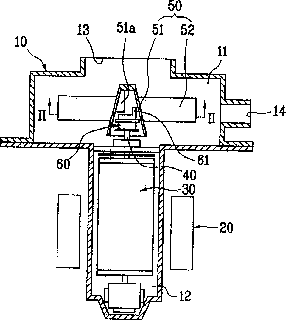
[0050] first, Figure 5 and Image 6 A drain pump according to an embodiment of the present invention is shown.
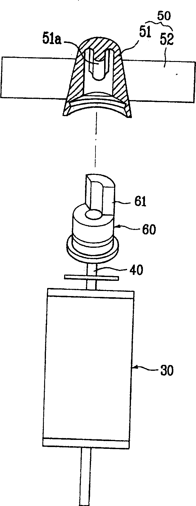
[0051] That is, the drainage pump according to the embodiment of the present invention generally includes the following components: the casing 100; the impeller 500; the rotating shaft 400; and the driving force transmission device.
[0052] Here, the casing 100 includes an impeller accommodating portion 110 for accommodating the impeller 500 and a rotor accommodating portion 120 for accommodating the rotor 300, and the casing constitutes the appearance of the drain pump.
[0053] At this time, the rotor accommodating portion 120 includes a rotor 300 made of permanent magnets. The stator 200 is provided on the outer periphery of the rotor housing portion 120 .
[0054] In addition, a suction port 130 for allowing washing water to flow into the impeller accommodating portion 110 is formed in the upper portion of the casing 100 . A discharge port 140 for discharging the inflowing washing water is formed on one side of the impeller accommodating portion 110 .
[0055] The structure of the above-mentioned housing 100 may be other various structures different from the above-mentioned structure. However, in the embodiment of the present invention, the structure of the casing is the same as that of the casing 10 of a conventional general drain pump.
[0056] In addition, the impeller 500 described above includes a head housing portion 510 and a plurality of blades 520 .
[0057] An impeller head 511 is formed to protrude at a certain portion of the inner peripheral surface of the head housing portion 510 . The plurality of vanes 520 are integrally formed around the periphery of the head housing portion 510 .
[0058] In addition, the rotating shaft 400 is integrally formed along the axis of the rotor 300 accommodated in the rotor accommodating portion 120 of the casing 100 . The function of the rotating shaft is to transmit the rotational force of the rotor 300 to the impeller 500 .
[0059] In addition, the most characteristic structure of the present invention is that the above-mentioned driving force transmission device is coupled to the end of the above-mentioned rotating shaft 400, and when the above-mentioned rotating shaft 400 rotates to a certain degree of activation force, the above-mentioned driving force transmission device will Contact with the impeller head 511 of the impeller 500 causes the impeller 500 to rotate.
[0060] The above-described driving force transmission device includes a coupling portion 710 and a restraining portion 720 .
[0061] The coupling portion 710 is axially coupled with the rotating shaft 400 .
[0062] In addition, the restraining portion 720 is provided on the surface of the coupling portion 710 , and when the starting force reaches a level capable of rotating the impeller 500 , the restraining portion will open toward the inner peripheral surface of the impeller 500 due to the action of the center force. , and hang on the impeller head 511 mentioned above.
[0063] exist Image 6 oblique view and Figure 7 The structure diagram of , specifically shows the structure of the above-mentioned restraining part 720 .
[0064] That is, the restraining portion 720 includes: at least one or more weights 721 in contact with the impeller head 511; one end is combined with the weights 721, and the other end is connected to at least one or more elastic members on the central portion of the upper surface of the combining portion 710 722.
[0065] The above-mentioned weight 721 is preferably made of metal material. This is so that the above-mentioned weight 721 can obtain sufficient center force.
[0066] In particular, it should be pointed out that the two sides of the above-mentioned weight 721 correspond to the shapes of the two sides of the above-mentioned impeller head 511 .
[0067] For example, the two sides of the impeller head 511 face the rotation direction of the rotating shaft 400 and are recessed inward, and the two sides of the weight 721 are recessed on both sides of the impeller head 511 .
[0068] In addition, in order to provide the weight 721 with a restoring force in the direction of the upper surface central portion of the coupling portion 710, the elastic member 722 is preferably formed by rounding in a clockwise or counterclockwise direction.
[0069] It should be pointed out that, in order to make the elastic member 722 have a certain elastic force, the elastic member is preferably made of a synthetic resin wire.
[0070] The unexplained reference numeral 722a is integrally formed with the coupling hook of the elastic member 722 described above. The function of the coupling hook 722 a is to couple the elastic member 722 to the weight 721 .
[0071] Next, the process of draining the water by the structure of the drain pump according to the embodiment of the present invention will be described.
[0072] First, as the draining process of the washing machine starts, power is supplied to the drain pump, and the rotor 300 will rotate along the periphery of the stator 200 .
[0073] Therefore, as the rotating shaft 400 rotates, the coupling portion 710 constituting the driving force transmission device will also rotate. Here, the rotating shaft is integrally formed along the axis of the rotor 300 .
[0074] At this time, in the initial start-up state in which the rotational force of the rotating shaft 400 is insufficient, only the coupling portion 710 rotates with the rotating shaft 400 , and the restricting portion 720 cannot be hooked on the impeller head 511 .
[0075] That is, the above-mentioned restraining portion 720, or maintains the Figure 7 The initial state shown (the state in which the elastic member 722 stays at the center portion of the surface of the joint portion 710 due to the restoring force of the elastic member 722 ), or it rotates in a slightly opened state within the range where it is not in contact with the impeller head 511 . Therefore, the impeller 500 cannot be rotated during the initial start-up.
[0076] However, after the rotation of the rotating shaft 400 is started, the weight 721 of the restraining portion 720 provided on the surface of the coupling portion 710 will obtain a center force due to the rotation of the coupling portion 710 . And due to the effect of the above-mentioned center force, it gradually moves toward the peripheral side of the above-mentioned joint portion 710 .
[0077] At this time, the elastic member 722 constituting the restraint portion 720 of the driving force transmission device gradually expands to the outside due to the center force of the weight 721 trying to escape to the outside.
[0078] Therefore, the weight 721 of the restraining portion 720 gradually rotates along the inner wall surface of the head housing portion 510 in which the impeller head 511 is formed, and contacts one of the side surfaces of the impeller head 511 during the rotation.
[0079] The above state is Figure 8 shown.
[0080] At this time, since the weight 721 is rotated with a sufficient starting force to release the initial restraint force of the impeller 500, the impeller 500 can be smoothly rotated.
[0081] Due to the rotation of the impeller 500, the washing water will flow into the impeller accommodating part 110 through the suction port 130 formed in the upper part of the casing 100, and the inflowing washing water will continue to be discharged through the discharge port 140 formed on the side of the impeller accommodating part 110.
[0082] In addition, once the above-mentioned series of processes are completed, that is, the draining process is completed, the power supply to the rotor will also be interrupted. Therefore, the rotation of the rotor 300 will also stop, and the rotation of the rotating shaft 400 will also gradually stop.
[0083] In addition, the rotation speed of the coupling portion 710 coupled to the rotating shaft 400 will also gradually decrease, and the center force of the weight of the restraining portion 720 will also gradually decrease.
[0084] At this time, due to the restoring force of the elastic member 722 constituting the restraining portion 720 , the weight 721 will gradually return to the original position, that is, the center side of the coupling portion 710 , thereby releasing the restraining force of the impeller head 511 .
[0085] As described above, the reason why the position of the weight 721 constituting the restraint portion 720 is returned to the original position is that when the drainage stroke is performed again, the restraint portion 720 can maintain a sufficient initial activation force before the restraint portion 720 obtains a sufficient initial activation force. The restraint with the impeller head 511 is released.
[0086] As a result, after the above-mentioned series of processes, the discharge stroke will be completed with the stop of the impeller 500 .
[0087] In addition, in the structure of the drainage pump according to the embodiment of the present invention, the shape of the elastic member 722 constituting the restraint portion 720 of the driving force transmission device is not limited to the shape of the aforementioned embodiment.
[0088] That is, it does not matter what the form is, as long as it is a structure in which the weight 721 can be fully opened to the outside when the center force is applied. When the center force of the weight 721 is released, the weight 721 may return to the original position so as not to restrain the impeller head 511 .
[0089] For example, it can be Figure 9 As shown, the above-mentioned elastic member 722 may be constituted by a coil spring.
[0090] Below, will refer to Figures 10 to 13 , the second embodiment of the drainage pump according to the present invention will be described in more detail.
[0091] first, Figure 10 and Figure 11 A drain pump according to a second embodiment of the present invention is shown.
[0092] That is, the drainage pump according to the embodiment of the present invention generally includes the following components: the casing 100 ; the impeller 500 ; the rotating shaft 400 ; the shaft coupling part 910 ;
[0093] Here, the casing 100 includes an impeller accommodating portion 110 for accommodating the impeller 500 and a rotor accommodating portion 120 for accommodating the rotor 300, and the casing constitutes the appearance of the drain pump.
[0094] At this time, the rotor accommodating portion 120 includes a rotor 300 made of permanent magnets. The stator 200 is provided on the outer periphery of the rotor housing portion 120 .
[0095] In addition, a suction port 130 for allowing washing water to flow into the impeller accommodating portion 110 is formed in the upper portion of the casing 100 . A discharge port 140 for discharging the inflowing washing water is formed on one side of the impeller accommodating portion 110 .
[0096] The structure of the above-mentioned housing 100 may be other various structures different from the above-mentioned structure. However, in the embodiment of the present invention, the structure of the casing is the same as that of the casing 10 of a conventional general drain pump.
[0097] In addition, the impeller 500 described above includes a head housing portion 510 and a plurality of blades 520 .
[0098] The above-described head housing portion 510 is in a state of being hollow inside. Each of the blades 520 is integrally formed along the outer peripheral surface of the head housing portion 510 .
[0099] In addition, the rotating shaft 400 is integrally formed along the axis of the rotor 300 accommodated in the rotor accommodating portion 120 of the casing 100 . The function of the rotating shaft is to transmit the rotational force of the rotor 300 to the impeller 500 .
[0100] In addition, the shaft coupling portion 910 rotates together with the rotary shaft 400 in a state in which the shaft is coupled to the rotary shaft 400 .
[0101] In addition, the function of the connection portion 920 is to transmit the starting force generated by the rotation of the shaft coupling portion 910 to the impeller 500 .
[0102] One end of the connecting portion 920 is connected to the shaft coupling portion 910 , and the other end is connected to the inner wall surface of the head housing portion 510 .
[0103]At this time, the length of the connection portion 920 is longer than the distance between the shaft coupling portion 910 and the inner wall surface of the head housing portion 510 constituting the impeller 500 . The most ideal length is: after the rotating shaft 400 rotates several times, a sufficient starting force is generated, and the impeller 500 can be rotated in a tight state.
[0104] The connection portion 920 as described above is preferably formed of a relatively thin wire that can be wound around the shaft coupling portion 910, and is preferably formed of a wire that is not easily broken.
[0105] It should be noted that, in the state where the connecting portion 920 is wound around the shaft coupling portion 910, if the rotation of the rotating shaft 400 stops, a restoring force in the opposite direction to the winding direction is provided, so that the connecting portion 920 can be removed from The above-mentioned shaft joint portion 910 is loosened, and the above-mentioned connecting portion should be composed of a wire having a certain elasticity.
[0106] In addition, the connection portion 920 and the shaft coupling portion 910 may be detachably connected, or may be integrally formed.
[0107] In addition, the connecting portion 920 and the inner wall surface of the head housing portion 510 may be integrally formed, but in this case, the manufacturing process becomes complicated.
[0108] Therefore, it is preferable that the connecting portion 920 and the inner wall surface of the head housing portion 510 of the impeller 500 are detachably coupled.
[0109] At this time, a retaining ring portion 911 is formed on the inner wall surface of the head accommodating portion 510 of the impeller 500, and a hook portion 921 that can be hung on the retaining ring portion 911 is formed at the end of the connecting portion 920. Therefore, the head accommodating portion 510 is connected to the The parts 920 are detachable.
[0110] In addition, in the above-mentioned structure, only one connection part 920 may be provided, but it is preferable to provide a plurality of connection parts for better operation.
[0111] However, if there are too many connection parts 920, the connection parts 920 may become entangled and the assembling work becomes difficult. Therefore, it is preferable to have two connection parts according to the embodiment of the present invention.
[0112] It should be particularly pointed out that, on a plane, the above-mentioned connecting portions 920 should be symmetrical with each other based on the shaft joint portion 910 .
[0113] That is, one end of each connecting portion 920 is connected to each other at the corresponding positions based on the center of the shaft coupling portion 910 , and the other end of each connecting portion 920 is connected to the corresponding position on the inner wall surface 510 .
[0114] Next, the process of draining the water according to the structure of the drain pump according to the second embodiment of the present invention will be described.
[0115] First, as the draining process of the washing machine starts, power is supplied to the drain pump, and the rotor 300 will rotate along the periphery of the stator 200 .
[0116] Therefore, the rotating shaft 400 coupled along the axis of the rotor 300 will rotate, and at the same time, due to the rotation of the rotating shaft 400, the shaft coupling portion 910 will also rotate.
[0117] At this time, if Figure 12 As shown, the connection portion 920 is in a loose state between the shaft coupling portion 910 and the inner wall surface of the head housing portion 510 of the impeller 500. Therefore, even if the shaft coupling portion 910 rotates with the rotation of the rotating shaft 400, in the initial stage, The connection portion does not transmit the rotational force of the rotating shaft 400 to the head housing portion 510 of the impeller 500 .
[0118] That is, in the initial stage of rotation of the rotating shaft 400 , the connecting portion 920 is simply wound around the periphery of the shaft coupling portion 910 .
[0119] However, as the number of rotations of the rotating shaft 400 increases, the connecting portion 920 wraps around the periphery of the shaft coupling portion 910 to the greatest extent possible, and the connecting portion 920 forms a tight space between the shaft coupling portion 910 and the inner wall surface of the head accommodating portion 510 . stretched state.
[0120] Therefore, the actuating force of the rotating shaft 400 is transmitted to the impeller 500 through the connecting portion 920 , thereby rotating the impeller 500 .
[0121] The above state is Figure 13 shown.
[0122] At this time, the above-mentioned rotating shaft 400 obtains a starting force larger than the restraining force provided to the above-mentioned impeller 500, and rotates. Therefore, the impeller 500 can finally be smoothly rotated.
[0123] Due to the rotation of the impeller 500, the washing water will flow into the impeller accommodating part 110 through the suction port 130 formed in the upper part of the casing 100, and the inflowing washing water will continue to be discharged through the discharge port 140 formed on the side of the impeller accommodating part 110.
[0124] In addition, once the aforementioned series of processes are completed, that is, the draining process is completed, the power supply to the rotor will also be interrupted. Therefore, the rotation of the rotor 300 will also stop, and the rotation of the rotating shaft 400 and the shaft joint 910 will also gradually stop.
[0125] As described above, once the rotation of the shaft coupling portion 910 is stopped, the shaft coupling portion 910 will rotate in the opposite direction due to the restoring force of the coupling portion 920 until the coupling portion 920 is restored. Therefore, as in the initial state, the connection portion 920 will be in a loose state between the shaft coupling portion 910 and the inner wall surface of the head housing portion 510 of the impeller 500 .
[0126] As described above, the reason why the connection portion 920 is restored to the loose state is to maintain the unconstrained state with the impeller 500 before the rotary shaft 400 obtains a sufficient initial activation force when the drain stroke is performed again.
[0127] As a result, after the above-mentioned series of processes, the discharge stroke will be completed with the stop of the impeller 500 .
PUM


Description & Claims & Application Information
We can also present the details of the Description, Claims and Application information to help users get a comprehensive understanding of the technical details of the patent, such as background art, summary of invention, brief description of drawings, description of embodiments, and other original content. On the other hand, users can also determine the specific scope of protection of the technology through the list of claims; as well as understand the changes in the life cycle of the technology with the presentation of the patent timeline. Login to view more.
Similar technology patents
Washing device and control method method
Owner:NANJING LG PANDA APPLIANCES
Container lid structure
InactiveCN107954071Adamage minimizationImprove the effect of initial washing
Owner:株式会社碧珍
Method and device for operating delivery pump
ActiveCN108980020Anoise minimization
Owner:ROBERT BOSCH GMBH
Method of reinforcing a bridge
InactiveCN101091023AImprove load capacitydamage minimization
Owner:INTELLIGENT ENG BAHAMAS
Classification and recommendation of technical efficacy words
- noise minimization
- damage minimization
Method and device for operating delivery pump
ActiveCN108980020Anoise minimization
Owner:ROBERT BOSCH GMBH
Method of reinforcing a bridge
InactiveCN101091023AImprove load capacitydamage minimization
Owner:INTELLIGENT ENG BAHAMAS
Washing device and control method method
Owner:NANJING LG PANDA APPLIANCES
Container lid structure
InactiveCN107954071Adamage minimizationImprove the effect of initial washing
Owner:株式会社碧珍