Electric connection box
A technology for electrical connection boxes and connectors, applied in electrical components and other directions, can solve problems such as short circuits, and achieve the effects of suppressing diffusion, expanding distance, and preventing short circuits.
- Summary
- Abstract
- Description
- Claims
- Application Information
AI Technical Summary
Problems solved by technology
Method used
Image
Examples
no. 1 approach
[0033] Referring to Figure 1 to Figure 5 A first embodiment of the present invention will be described.
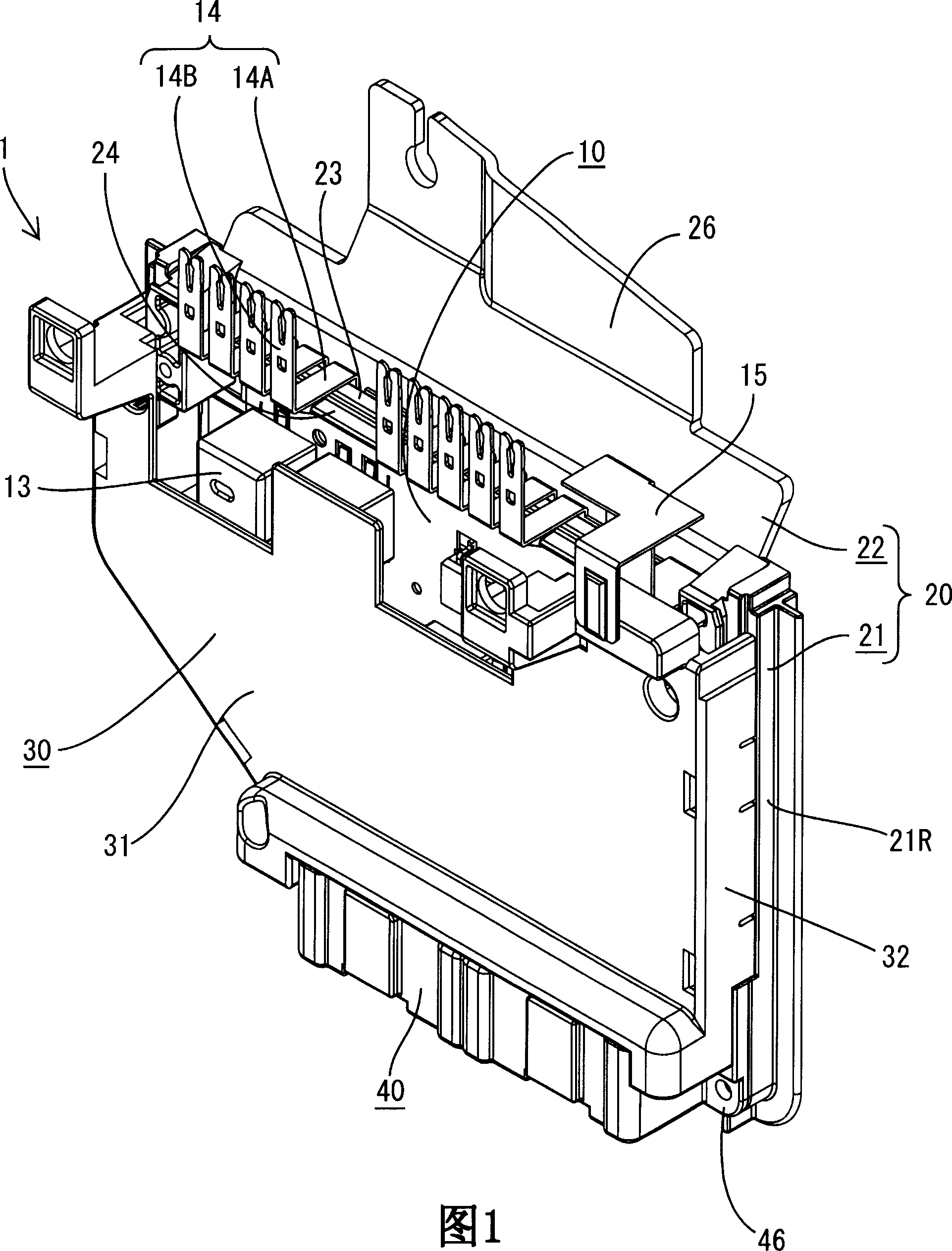
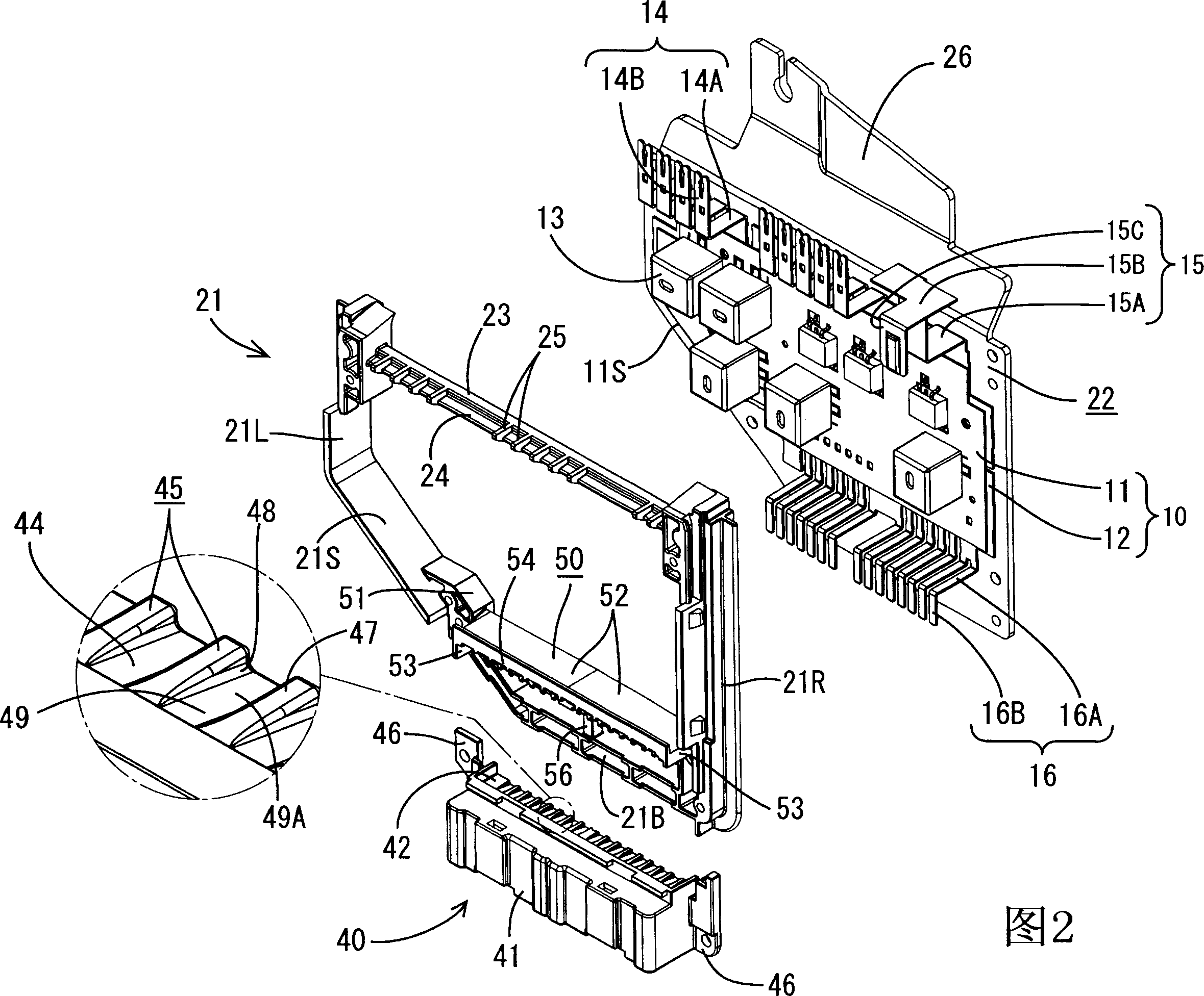
[0034] FIG. 1 is an external perspective view of an electrical connection box 1 of the present embodiment. FIG. 2 is a perspective view showing a state before the frame body 21 and the lower connection body 40 are assembled on the circuit configuration body 10 .
[0035] Hereinafter, regarding the direction of each component constituting the electrical connection box 1, the left front side (cover 30 side) in FIG. , The bottom side is the bottom, the right side is the right side, and the left side is the left side.
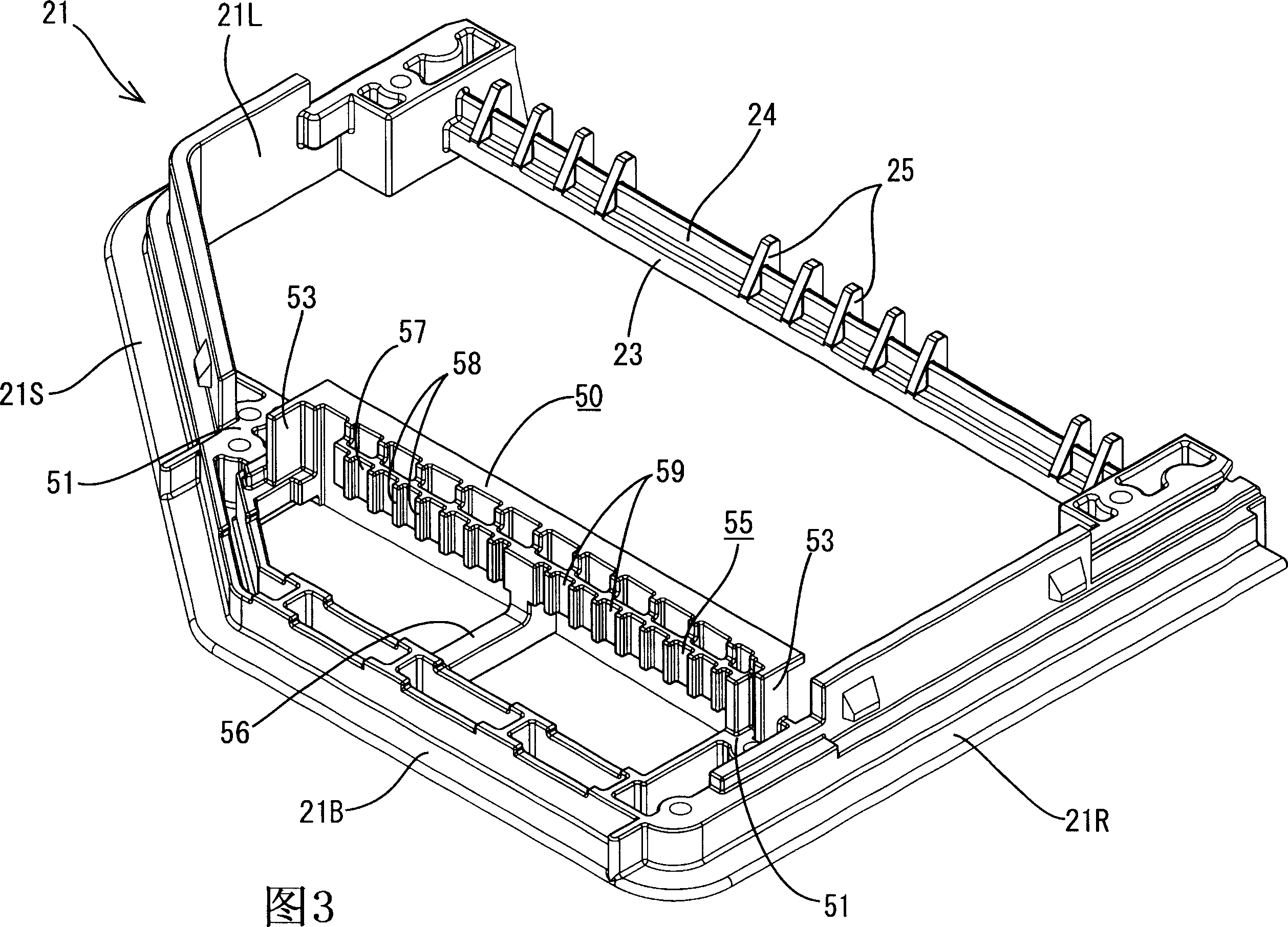
[0036] Electrical junction box 1, as shown in Figure 1 and Figure 2, will have the circuit structure body 10 of circuit board 11 and bus bar (bus-bar) 12, vertically place and accommodate in the box body 20 that is made of frame body 21 and radiator plate 22 and cover the front side of the box body 20 with a cover 30 .
[0037] The circuit board 11 constitu...
no. 2 approach
[0072] Referring to Fig. 6, Fig. 7, Figure 8 A second embodiment of the present invention will be described.
[0073] 6 is a perspective view showing a state before the frame body 21 and the lower connector 40 are assembled to the circuit structure 10 in the electrical connection box 60 according to the second embodiment. FIG. 7 is a side sectional view of an electrical connection box 60 according to the second embodiment. Figure 8 It is a partially enlarged cross-sectional view showing a state in which the horizontal portion 16A of the lower bus bar terminal 16 is sandwiched between the first rib 45 and the second rib 58 in the electrical junction box 60 according to the second embodiment.
[0074] The electrical junction box 60 according to the second embodiment differs from the electrical junction box 1 according to the first embodiment in that the narrow portion 18 is provided on the horizontal portion 16A of the lower bus bar terminal 16 . The other configurations are...
no. 3 approach
[0083] A third embodiment of the present invention will be described below with reference to FIG. 9 .
[0084] FIG. 9 is a side sectional view of an electrical connection box 70 according to the third embodiment.
[0085] The electrical junction box 70 according to the third embodiment is different from the first embodiment or the second embodiment in that the displacement restricting portion 55 is not provided at the lower portion of the waterproof wall 50 . That is, in the third embodiment, the displacement restricting portion 55 that restricts the upward displacement of the horizontal portion 16A by pressing the horizontal portion 16A of the lower bus bar terminal 16 from above is not provided. In addition, the other configurations are the same as those of the first or second embodiment, so the same reference numerals are used, and repeated descriptions are omitted.
[0086] When the lower connector 40 of the electrical junction box 70 is fitted with an external connector,...
PUM
 Abstract
Description
Claims
Application Information
 - R&D
- Intellectual Property
- Life Sciences
- Materials
- Tech Scout
- Unparalleled Data Quality
- Higher Quality Content
- 60% Fewer Hallucinations
Browse by: Latest US Patents, China's latest patents, Technical Efficacy Thesaurus, Application Domain, Technology Topic, Popular Technical Reports.
© 2025 PatSnap. All rights reserved.Legal|Privacy policy|Modern Slavery Act Transparency Statement|Sitemap|About US| Contact US: help@patsnap.com


