Method for realizing parts detection utilizing intelligent equipment firmware

A technology implemented by smart devices and firmware. The redundancy applied in the operation is used for data error detection, response error generation, program loading/starting, etc., which can solve problems such as inconvenient operation, clutter, and incomplete fault information. To achieve the effect of simple operation and not easy to lose

Active Publication Date: 2007-01-03
LENOVO (BEIJING) CO LTD
View PDF0 Cites 6 Cited by
  • Summary
  • Abstract
  • Description
  • Claims
  • Application Information

AI Technical Summary

Problems solved by technology

[0009] 1. Since the self-inspection function in the existing POST process is relatively simple, it can only detect whether a certain part of the device is faulty, but cannot further detect the type and scope of the fault, so the depth and breadth of detection are limited. Not enough, the output fault information is incomplete, not enough for engineers to judge the detailed fault type
[0010] 2. The above diagnostic card is only based on the output of different output devices according to the content of the POST process, that is, the detection content is output on the diagnostic card with a digital LED indicator instead of the alarm output of the main board, so it is still subject to POST’s automatic output. Due to the limitation of detection and diagnosis capabilities, the depth and breadth of de

Method used


Image

  • Method for realizing parts detection utilizing intelligent equipment firmware
  • Method for realizing parts detection utilizing intelligent equipment firmware
  • Method for realizing parts detection utilizing intelligent equipment firmware

Examples


Example

[0068] The first application example:

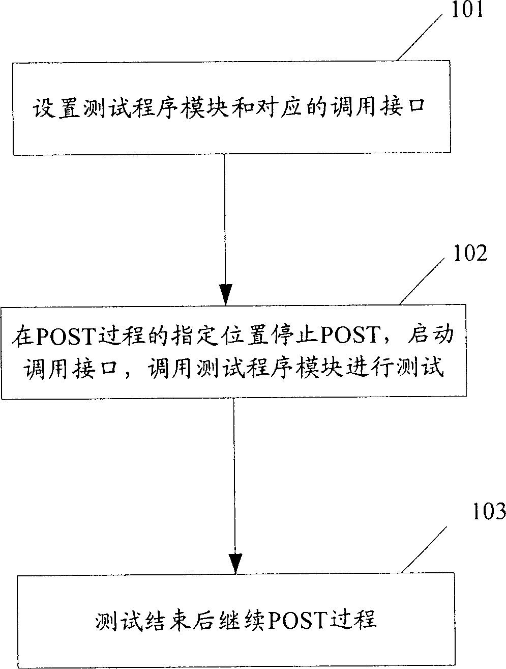
[0069] Because many times computer users will encounter the computer "no display" failure, that is, press the power button on the computer chassis, under normal circumstances, the computer should execute the BIOS POST process, and display the manufacturer's LOGO or self-check information on the display screen , But sometimes there will be a failure that the monitor does not display after booting. Normally, in addition to the above information, computer users cannot provide more valuable information.

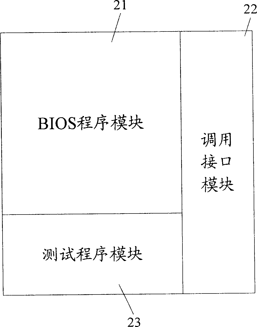
[0070] Using the method of the present invention, a test program module can be added to the BIOS. The function of the test program module is only to make the buzzer or horn on the main board emit a short high-frequency short sound. Since the test program does not have a necessary POST preparation stage, the calling interface of the test program module is set at the point where the computer is powered on and the CPU starts to execute the instruc...

Example

[0075] Second application example:

[0076] In this example, a memory test program module, a CMOS test program module, and a hard disk test program module are embedded in the BIOS. For the process of this example, please refer to Figure 4 , Assuming Figure 4 Where n is 3, where the memory test program module, CMOS test program module, and hard disk test program module correspond to Figure 4 The first, second, and third test program modules in. The computer is powered on, and after POST phase 1 is executed, the POST process is suspended, the call interface 1 corresponding to the memory test program module is started, and the state value of trigger condition 1 is judged. If the trigger condition 1 is valid, the memory test program is called to execute. And the test result information is output in a standardized form through the output device of the computer. The output device can be a buzzer, speaker, display, etc.; for example, the test result of the buzzer is shown in Table 1:

...


PUM


Abstract

The invention discloses a method to detect the parts by the firmware of the intelligent device. It sets the detecting program module in the intelligent device and detects the correspondent transferring interface in the POST process. The method includes: the intelligent runs the POST process after starting, when it runs to the location of the transferring interface, the POST process is interrupted and starts the transferring interface to detect the device parts and outputs the detecting results. When the detect finishes, the POST process is run continuously. The invention can detect the parts deeply and widely in the POST process of the intelligent device.

Description

technical field [0001] The invention relates to a fault detection or monitoring technology of an intelligent device, in particular to a method for realizing component detection by using firmware of an intelligent device. Background technique [0002] Currently, smart devices such as personal computers, palmtop computers, and smart computing devices are more and more widely used, among which the application of personal computers is particularly prominent. However, the components in these smart devices have a probability of failure, which has a great negative impact on the production, use and maintenance of smart devices. [0003] In order to detect whether the components in the smart device are working normally, there are mainly two existing technical solutions: [0004] Prior art 1. A power-on self-test (POST) solution for smart devices. [0005] The current smart device initializes its own system through the POST process. The initialization process includes a simple detec...

Claims


Application Information

Patent Timeline
IPC IPC(8): G06F11/14G06F9/445
Inventor 王晓文刘涛龚仲涛樊小军
Owner LENOVO (BEIJING) CO LTD
Why Eureka
Try Eureka