Manufacture of dental prostheses

A technology of dentures and data, applied in the field of the shape of dental bridges, can solve problems that require labor and time-consuming

Inactive Publication Date: 2007-01-03
RENISHAW PLC
View PDF2 Cites 11 Cited by
  • Summary
  • Abstract
  • Description
  • Claims
  • Application Information

AI Technical Summary

Problems solved by technology

The waxing phase of the described procedure is not only time consuming, but also requires skilled labor

Method used


Image

  • Manufacture of dental prostheses
  • Manufacture of dental prostheses
  • Manufacture of dental prostheses

Examples


Embodiment Construction

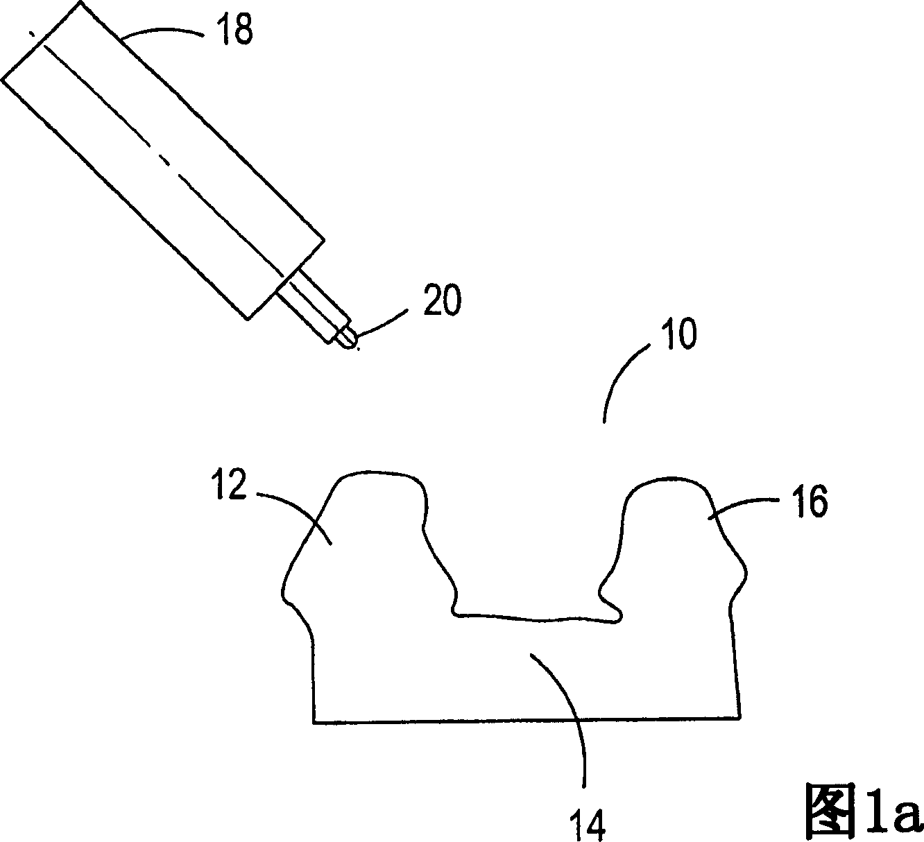
[0021] FIG. 1 a shows a tooth blank 10 , which in this example comprises a first fixing body 12 , a connecting portion 14 and a second fixing body 16 . The first and second fixing bodies are positioned on opposite sides of the connecting portion 14 . The connecting portion 14 is the location of the missing tooth to be replaced by the bridge artificial tooth or pontic.

[0022] The surfaces of the first and second fixed bodies 12 , 16 and the connection part 14 are scanned using a probe 18 with a scanning tip 20 . This can be done as a single module, for example by CT (Computed Axial Tomography) or MRI (Magnetic Resonance Imaging) scan or using a non-contact scanning device as described in US Patent No. 6,217,334. The data from the scan represent the inner surface of the crown that will be fabricated to cover the first and second fixtures.

[0023] Optionally, the different features of the model are segmented to allow a thorough scan of each feature to be formed. An initial ...


PUM


Abstract

A method of determining the shape of a dental prosthesis is disclosed comprising, scanning at least a connecting portion (14) of a preparation (10), wherein the preparation (10) comprises a first anchor (12) and a connecting portion (14) connected thereto, forming a physical model on the connecting portion (14) to produce a pontic (22), and scanning at least the pontic (22) whereby the surface of the first anchor (12) is also scanned during a scanning step whereby the scanning steps can be carried out in either order. The preparation (10) may be scanned to provide data concerning relative locations of the first anchor (12) and connecting portion (14), which may be used to align data obtained during the scanning steps. Also disclosed is a method of producing a model of a dental prosthesis and a method of manufacturing a dental prosthesis.

Description

technical field [0001] The present invention relates to a method of determining the shape of a dental prosthesis, more particularly a bridge. Background technique [0002] Dental blanks are usually provided in the manufacture of dental bridges. This dental blank is often a frontal plaster impression of the part of the mouth that needs the bridge to function. It consists of at least two anchors on either side of the missing tooth. The dental blank is scanned to provide internal dimensions of the dental bridge. Next, wax is poured over the anchor layer and the edentulous position where the pontic or replacement tooth is to be formed to produce the desired shape of the bridge. The fixture requires only a thin layer of wax representing the thickness of the coping resting on the surface of the fixture to support the bridge. Once the waxing is complete, it serves as the pattern for the waxing process and the alloy is used to form the final bridge. The waxing phase of the proc...

Claims


Application Information

Patent Timeline
Patent Type & Authority Applications(China)
IPC IPC(8): A61C13/00A61C5/77
CPCA61C13/0004
Inventor 奈杰尔·史蒂芬·沃克曼布赖恩·蒂莫西·布勒特斯
Owner RENISHAW PLC
Why Eureka
Try Eureka