Dental prosthesis manufacturing process, dental prosthesis pattern & dental prosthesis made thereby

a technology for dental prosthesis and manufacturing process, which is applied in the field of dental prosthesis manufacturing process, dental prosthesis pattern & dental prosthesis made thereby, can solve the problems of image based on the original, impractical to make dental prosthesis from gold and platinum using this technology, and great utilization of this technology

Inactive Publication Date: 2005-07-05
NAT DENTEX LLC
View PDF8 Cites 66 Cited by
  • Summary
  • Abstract
  • Description
  • Claims
  • Application Information

AI Technical Summary

Benefits of technology

[0007](2) improved accuracy of the marginal edges of the dental prosthesis positioned along the margins of a tooth structure, and
[0008](3) reduction of time to make a dental prosthesis using conventional investment casting techniques.
[0013]In accordance with this invention, the pattern has marginal edges that are at least ¾ of a millimeter from margins of an individual tooth structure to which the dental prosthesis is to be attached. These set back marginal edges of the pattern are manually adjusted to compensate for the specific configuration of the individual tooth structure by adding wax material to these set back marginal edges. This insures that the inaccuracies ordinarily occurring using computer aided design and milling equipment are avoided.

Problems solved by technology

Although this computer aided design equipment proposes to eliminate conventional investment casting, it suffers from a number of drawbacks that prevent greater utilization of this technology.
First, it is impractical to make dental prosthesis from such precious metals as gold and platinum using this technology because so much of the precious metal is lost during the milling process.
Second, the adjustments made to the image based on the original data collected during scanning usually fail to create a dental prosthesis that properly fits into the patient's mouth.

Method used


Image

  • Dental prosthesis manufacturing process, dental prosthesis pattern & dental prosthesis made thereby
  • Dental prosthesis manufacturing process, dental prosthesis pattern & dental prosthesis made thereby
  • Dental prosthesis manufacturing process, dental prosthesis pattern & dental prosthesis made thereby

Examples


Embodiment Construction

,” one will understand how the features of this invention provide its benefits, which include, but are not limited to,

[0006](1) usage of precious metal in making a dental prosthesis with minimum waste of such metal,

[0007](2) improved accuracy of the marginal edges of the dental prosthesis positioned along the margins of a tooth structure, and

[0008](3) reduction of time to make a dental prosthesis using conventional investment casting techniques.

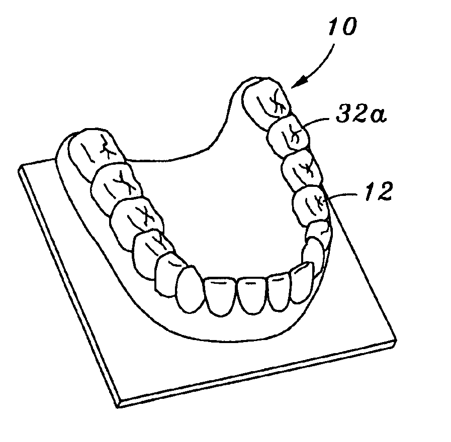
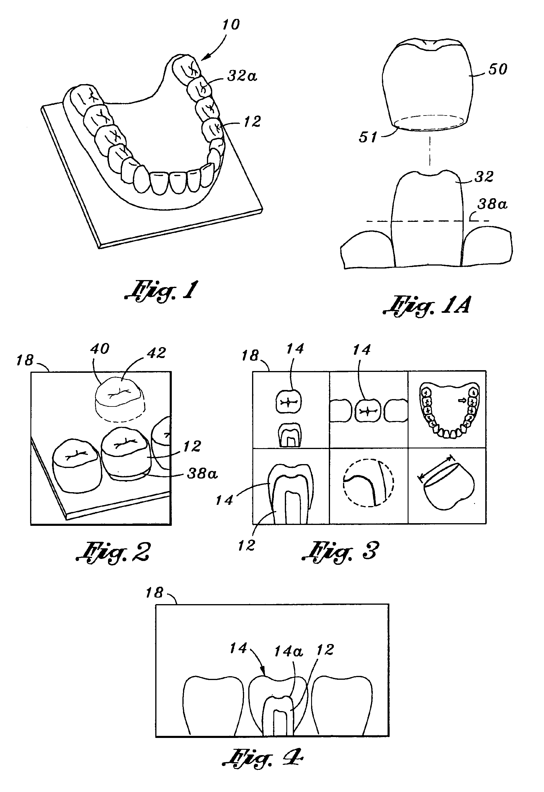
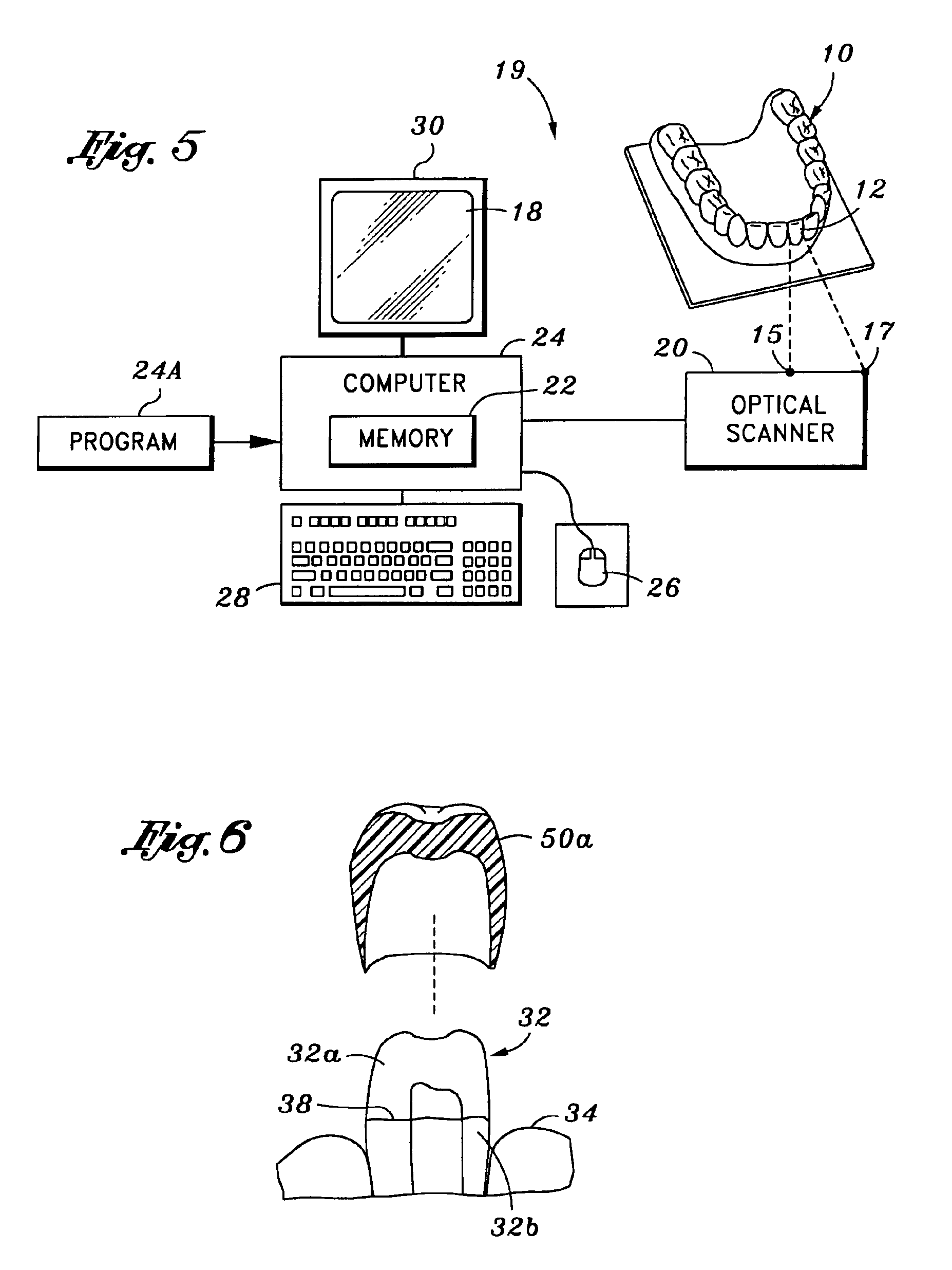
[0009]The invention includes a method of manufacturing a pattern of a dental prosthesis from a wax material, a method of manufacturing a dental prosthesis itself using this pattern, the dental prosthesis itself, and the pattern used in the manufacture of the dental prosthesis. As used herein, a dental prosthesis includes wax-ups (a term used in the industry) of articulated jaws. These wax-ups constitute an entire array of the teeth in an individual patient and they are used for diagnostic purposes. As used herein, “wax material” includes waxe...


PUM


Abstract

A dental prosthesis is made by first forming a model of a patient's dentition. A three dimensional digital data corresponding to the surfaces of the model is then created. Based on this data, a three dimensional digital data file is then created substantially corresponding to the dental prosthesis to be manufactured. The three dimensional digital data of the dental prosthesis to be manufactured is next transmitted to automated prototyping equipment, and using the automated prototyping equipment, a wax pattern of the dental prosthesis is manufactured based upon this three dimensional digital data of the dental prosthesis. Finally, using this wax pattern in the lost wax investment casting process, the dental prosthesis is made. Prior to investment casting, marginal edges of the wax pattern are adjusted manually.

Description

BACKGROUND OF THE INVENTION[0001]Computer technology has advanced to the point where a dental prosthesis may be milled from a solid block of material based on three-dimensional digital data corresponding to a proposed shape of the dental prosthesis. The dentist first makes an impression of a patient's existing dentition. Typically, this includes nearby surfaces where the prosthesis is to be located in the patient's mouth. This is accomplished by the dentist first drilling away any unwanted dental tooth structure and then having the patient bite into an impression material that forms a negative impression of the patient's dentition, including the tooth structure to which the dental prosthesis is to be attached. This negative impression is then filled with dental die stone to make a model of the tooth structure to which the dental prosthesis is to be attached and adjacent teeth, particularly the teeth immediately above and to the sides of the tooth structure to which the dental prosth...

Claims


Application Information

Patent Timeline
Patent Type & Authority Patents(United States)
IPC IPC(8): A61C13/00A61C5/77G16Z99/00
CPCA61C13/0004A61B2034/102G16H50/50B33Y70/00B33Y80/00A61C5/77G16Z99/00G16H20/40B33Y40/20
Inventor O'BRIEN, MICHAEL J.LUKSCH, DERRICK G.
Owner NAT DENTEX LLC
Why Eureka
Try Eureka