Three-dimensional occlusal and interproximal contact detection and display using virtual tooth models

a virtual tooth and occlusal technology, applied in the field of dental and orthodontics, can solve the problems of inability to confirm, requires an extreme amount of time and labor, and is too expensive, and achieves the effect of optimizing the interproximal and occlusal relationship, positioning and/or orientation, and optimizing the shape and position

Inactive Publication Date: 2005-05-05
ORAMETRIX
View PDF10 Cites 67 Cited by
  • Summary
  • Abstract
  • Description
  • Claims
  • Application Information

AI Technical Summary

Benefits of technology

[0026] As another embodiment of the invention, the feature of determining distances between teeth and displaying such information can be used to determine interproximal points of contact. The feature can be extended to determining interproximal and occlusal contact for virtual prosthetic devices, such as crowns and bridges. The determination of such contacts on a compute allows the clinician to evaluate the prosthetic device and optimize its shape, position and/or orientation so as to maximize its interproximal and occlusal relationship to adjacent and opposing teeth.
[0027] In still another aspect, the use of contact information can enable a “magnetic” function by which teeth are automatically positioned in close proximity or touching contact with an adjacent tooth or an opposing tooth. In particular, a method is provided of manipulating virtual teeth on a user interface of a general-purpose computer, the

Problems solved by technology

However, it is obvious that such an approach requires an extreme amount of time and labor and thus is too costly, and this is the reason why it is not practiced widely.
There is no way to confirm whether the brackets are placed correctly; and misplacement of the bracket will change the direction and/or magnitude of the forces imparted on the teeth.
While at the beginning of treatment things generally run well as all teeth start to move at least into the right direction, at the end of treat

Method used


Image

  • Three-dimensional occlusal and interproximal contact detection and display using virtual tooth models
  • Three-dimensional occlusal and interproximal contact detection and display using virtual tooth models
  • Three-dimensional occlusal and interproximal contact detection and display using virtual tooth models

Examples


Embodiment Construction

Overview

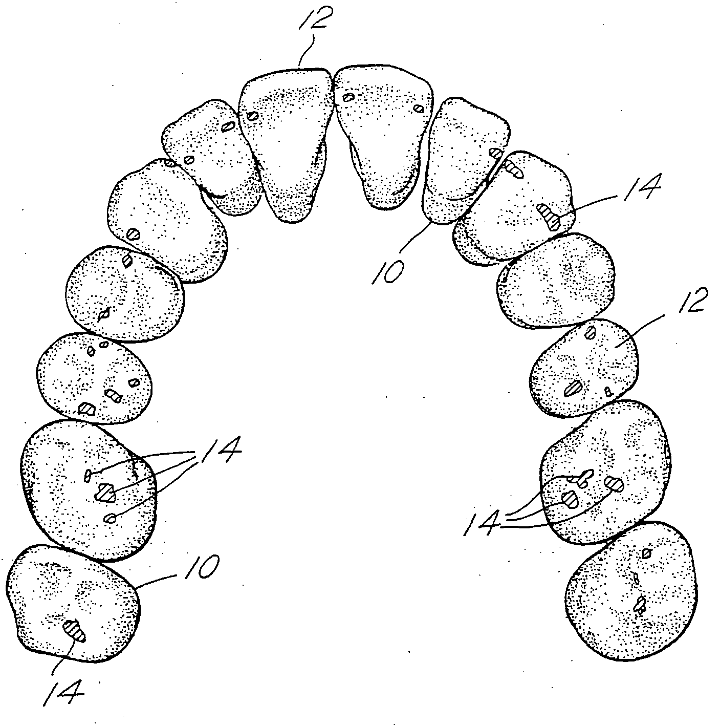
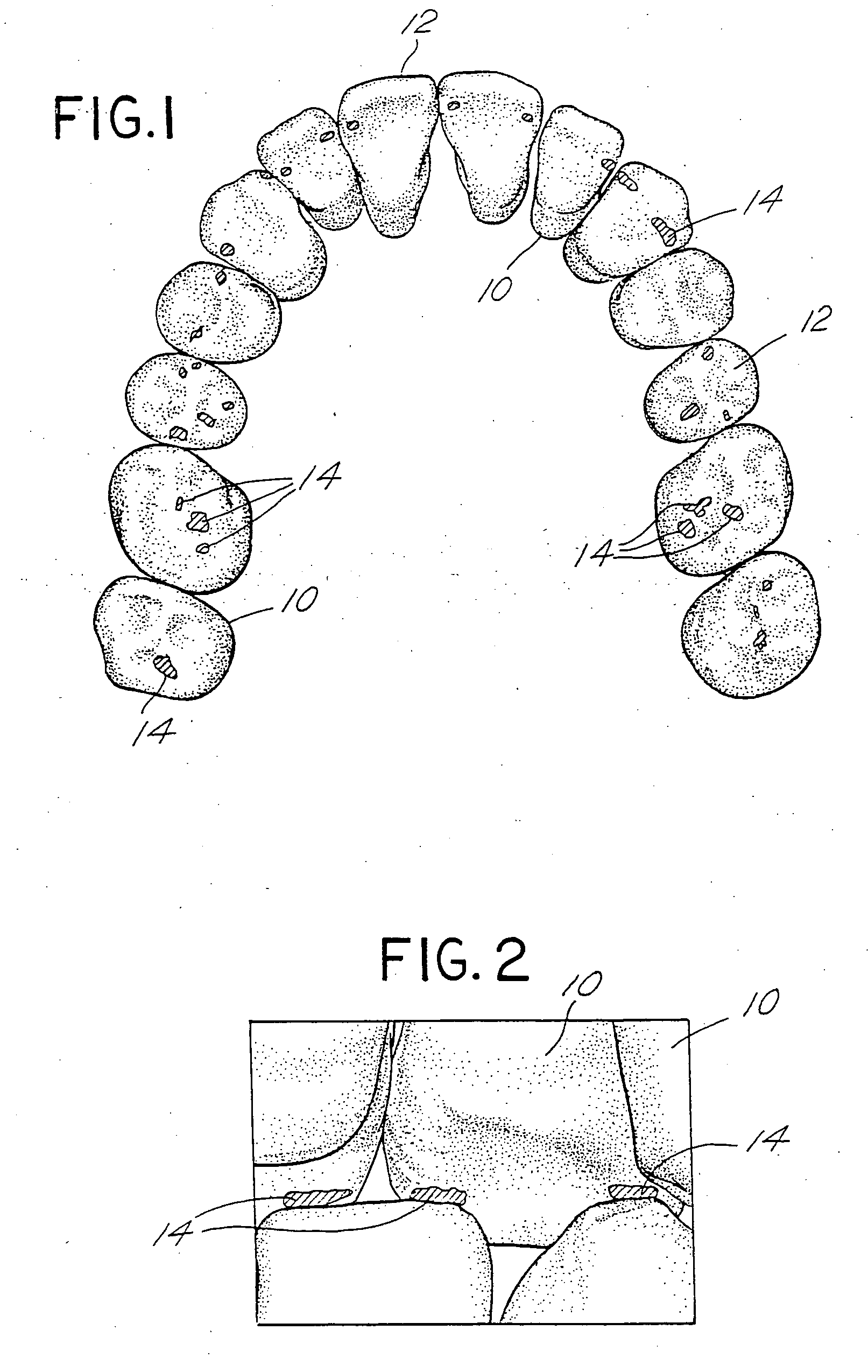
[0040] The determination and display of occlusal contacts between teeth in the upper and lower jaws in accordance with a preferred embodiment of the invention makes use of three-dimensional virtual models of teeth. The virtual models of teeth are stored in a memory and available to a general-purpose computer. As is known in the art, virtual models of teeth of a patient can be obtained by using a laser scanner to scan a physical model of the dentition. Alternatively, the teeth can be scanned in vivo, or a model of the dentition can be scanned, by a hand-held scanner such as the type described in published PCT application of OraMetrix, Inc., PCT / US01 / 11969, publication no. WO 01 / 80761, the entire contents of which is incorporated by reference herein.

[0041] Once the teeth have been scanned, the three-dimensional scan data can be represented in a a computer and displayed to the user as a three-dimensional model. There are a variety of techniques known in the CAD / CAM art for r...


PUM


Abstract

Occlusal contact between upper and lower virtual three-dimensional teeth of a patient when the upper and lower arches are in an occlused condition are determined and displayed to the user on a user interface of a general purpose computing device. Various techniques for determining occlusal contacts are described. The areas where occlusal contact occurs is displayed on the user interface in a readily perceptible manner, such as by showing the occlusal contacts in green. If the proposed set-up would result in a interpenetration of teeth in opposing arches, such locations of interpenetration are illustrated in a contrasting color or shading (e.g., red). The ability to calculate distances and display occlusal contacts in a proposed set-up assists the user in planning treatment for the patient. The process can be extended to interproximal contact detection as well. The concepts also apply to dental prosthetics, such as crowns, fillings and dentures.

Description

CROSS-REFERENCE TO RELATED APPLICATIONS [0001] This is a continuation in part of U.S. patent application Ser. No. 09 / 835,031 filed Apr. 13, 2001, which is a continuation in part of Ser. No. 09 / 560,640 filed Apr. 28, 2000 and Ser. No. 09 / 451,609 filed Nov. 30, 1999, now U.S. Pat. No. 6,250,918. This is also a continuation in part of U.S. patent application Ser. No. 09 / 835,039 filed Apr. 13, 2001. The entire contents of each of the related applications and patents is incorporated by reference herein.BACKGROUND OF THE INVENTION [0002] A. Field of the Invention [0003] This invention relates generally to the fields of dentistry and orthodontics. More particularly, the invention relates to methods for evaluating the areas of contact, and near contact, between upper and lower teeth when the upper and lower arches are in a closed or occluded condition. Knowledge of such areas of contact (“occlusal contacts” herein) is helpful in planning orthodontic treatment. The present invention provides...

Claims


Application Information

Patent Timeline
IPC IPC(8): A61C7/00A61C7/14A61C9/00A61C13/00A61C13/097A61C19/04A61F2/30G16H20/30G16H30/40
CPCG06F19/3481G06T2210/21A61C13/0004A61C19/04A61C9/0053A61C13/097G06T2219/2012G06F19/3437A61C7/002G06T17/00A61F2002/30953G06T19/20A61C7/146A61C7/00G16H50/50B33Y80/00B33Y50/00B33Y70/00G16H20/30G16H30/40G16H20/40
Inventor SPORBERT, PEERIMGRUND, HANSKOUZIAN, DIMITRIJMAETZEL, STEPHANSACHDEVA, ROHITRUBBERT, RUDGER
Owner ORAMETRIX
Why Eureka
Try Eureka