Supercharge Your Innovation With Domain-Expert AI Agents!

Optical coating device

A technology of optical coating and coating chamber, applied in sputtering coating, ion implantation coating, vacuum evaporation coating, etc., which can solve the problems of coating uniformity error, poor coating uniformity, evaporation range and angle difference, etc. , to achieve the effect of correcting the uniformity

Inactive Publication Date: 2007-01-10
HONG FU JIN PRECISION IND (SHENZHEN) CO LTD +1
View PDF0 Cites 9 Cited by
  • Summary
  • Abstract
  • Description
  • Claims
  • Application Information

AI Technical Summary

Problems solved by technology

But if it is necessary to make optical components with higher precision, a better method is needed to solve the error of coating uniformity caused by using a single correction plate
Especially when using more than one evaporation material to make optical components, because the size of the evaporated particles is different, the evaporation range and angle of different materials are different. If only a single correction plate is used, the coating uniformity may be caused by the relationship between different materials. Not good, so that the high-precision requirements cannot be achieved

Method used


Image

  • Optical coating device

Examples


Embodiment Construction

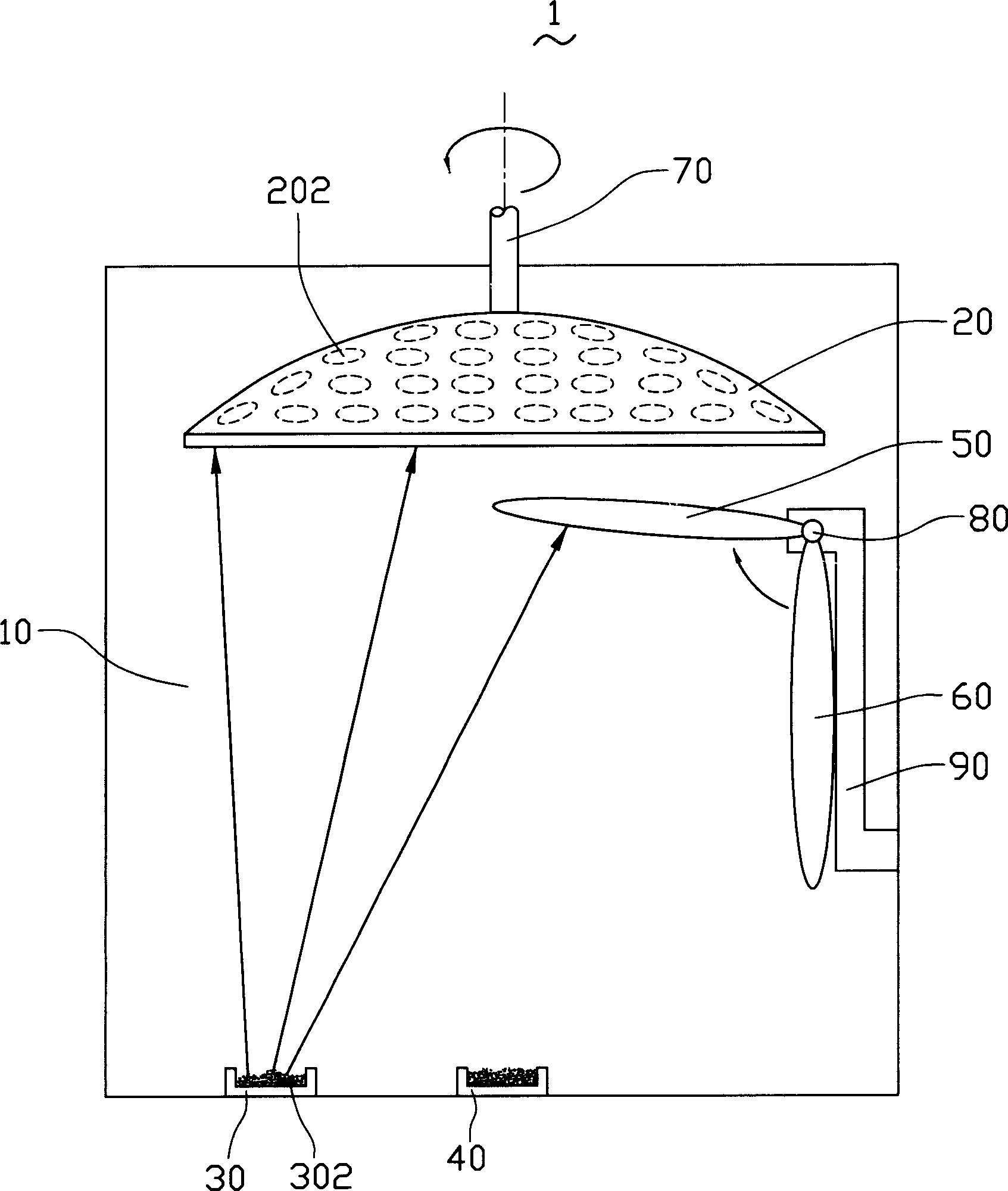
[0009] see figure 1 As shown, the optical coating device 1 of the preferred embodiment of the present invention includes a vacuum coating chamber 10 , a substrate carrying mechanism 20 , a first crucible system 30 , a second crucible system 40 , a first correction plate 50 and a second correction plate 60 .

[0010] The inside of the vacuum coating chamber 10 is a sealed vacuum environment. The substrate carrying mechanism 20 is umbrella-shaped, and is detachably installed on the upper part of the vacuum coating chamber 10, and the substrate carrying mechanism 20 is provided with a plurality of substrate fixing positions 202, and the plurality of substrate fixing positions 202 can hold multiple substrates during coating. A substrate is fixed thereon, and the substrate carrying mechanism 20 is also provided with a driving device 70, which can drive the substrate carrying mechanism 20 to rotate at a high speed during film coating.

[0011] The first crucible system 30 and the s...


PUM


Abstract

The invention relates to an optical coating device that includes vacuum coating room, base board bearing structure, plural crucible system and plural modification boards. The base board bearing structure is set at the upper part of vacuum coating room, and the crucible system is located at the down part of the base board bearing structure. The plural modification boards are set between the base board bearing structure and the crucible system through the cover of rotating structure.

Description

【Technical field】 [0001] The invention relates to an optical coating device, in particular to an optical coating device with uniform coating. 【Background technique】 [0002] At present, optical thin films are widely used in optical instruments, such as sensors, semiconductor lasers, interferometers, glasses, and optical fiber communication components, and many other fields. Optical thin films usually achieve their expected effects through interference, which refers to coating one or more layers of dielectric films or metal films on optical components or independent substrates to change the transmission characteristics of light waves. [0003] At present, the production of optical thin films is usually based on physical vapor deposition (Physics Vapor Deposition, referred to as PVD). Reaching the surface of the substrate, after the material reaches the surface of the substrate, it will be deposited and gradually form a thin film. Usually, in order to produce high-purity thi...

Claims


Application Information

Patent Timeline
Patent Type & Authority Applications(China)
IPC IPC(8): C23C14/00C23C14/24C23C14/30
CPCC23C14/044
Inventor 简士哲
Owner HONG FU JIN PRECISION IND (SHENZHEN) CO LTD
Features
  • R&D
  • Intellectual Property
  • Life Sciences
  • Materials
  • Tech Scout
  • Unparalleled Data Quality
  • Higher Quality Content
  • 60% Fewer Hallucinations
Learn More