Colour filtering baseboard and its making method
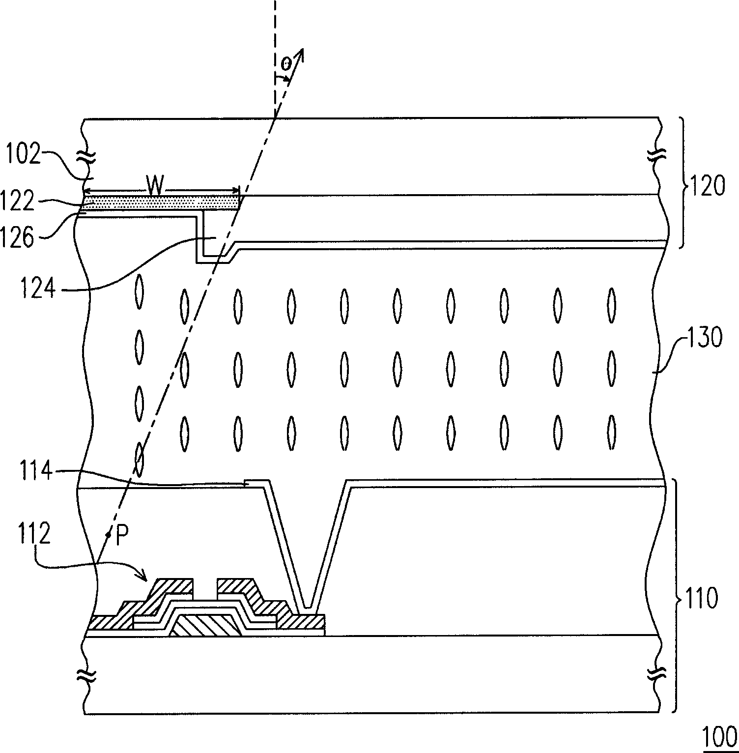
A technology of a color filter substrate and a manufacturing method, applied in optics, optical elements, nonlinear optics, etc., capable of solving problems such as reducing the aperture ratio of a display panel 100
- Summary
- Abstract
- Description
- Claims
- Application Information
AI Technical Summary
Problems solved by technology
Method used
Image
Examples
no. 1 example
[0065] Figure 4A It is a three-dimensional schematic diagram of the color filter substrate for completing the black matrix in the first embodiment of the present invention. Figure 4B From Figure 4D to Figure 4A Sectional view of subsequent manufacturing process. Please refer to Figure 4A Firstly, a substrate 400 with a plurality of pixel regions 402 is provided, and a plurality of striped patterns 412 are formed between these pixel regions 402 to form a black matrix 410 on the substrate 400 .
[0066] It should be noted that the color filter patterns (not shown in the figure) formed in the subsequent manufacturing process are arranged in these pixel regions 402 . Those skilled in the art should know that most of the subsequently formed color filter patterns include red filter patterns, green filter patterns and blue filter patterns, and the arrangement of these filter patterns on the substrate 400 can be The mosaic type, triangle type, stripe type or four pixel type ar...
no. 2 example
[0081] Figure 9A to Figure 9D These are the cross-sectional views of the manufacturing process of the color filter substrate in the second embodiment of the present invention in sequence. It is worth noting that the black matrix formed by the method of this embodiment is also composed of a plurality of striped patterns whose sides are away from the substrate and extend to the edge of the adjacent pixel area. The details of such strips will be described below. The method of forming the shape pattern.
[0082] Please refer to Figure 9A Firstly, a substrate 400 with a plurality of pixel regions 402 is provided, and a plurality of auxiliary patterns 904 are formed on the substrate 400 . Wherein, each auxiliary pattern 904 extends from the corresponding pixel area 402 to the periphery of the pixel area 402 . That is to say, the auxiliary pattern 904 covers the substrate 400 in the pixel area 402 , and its area is larger than that of the pixel area 402 .
[0083] Please refer ...
no. 3 example
[0090] Figure 12A to Figure 12D It is a cross-sectional view of the manufacturing process of the color filter substrate in the third embodiment of the present invention in sequence. Please refer to Figure 12A First, a plurality of color filter patterns 510 are formed on the substrate 500, and the formation method, material and arrangement of these color filter patterns 510 are, for example, the same as the color filter patterns 410 of the first and second embodiments, I won't repeat them here. In addition, in order to accurately form the color filter patterns 510 at predetermined positions on the substrate 500 , alignment marks (not shown) are usually made on the substrate 500 before forming the color filter patterns 510 . In this embodiment, for example, before forming the color filter pattern 510 , a laser chemical vapor deposition process is performed to form an alignment mark on the substrate 500 . After that, color filter patterns 510 are formed on the substrate 500 ...
PUM
 Abstract
Description
Claims
Application Information
 - R&D Engineer
- R&D Manager
- IP Professional
- Industry Leading Data Capabilities
- Powerful AI technology
- Patent DNA Extraction
Browse by: Latest US Patents, China's latest patents, Technical Efficacy Thesaurus, Application Domain, Technology Topic, Popular Technical Reports.
© 2024 PatSnap. All rights reserved.Legal|Privacy policy|Modern Slavery Act Transparency Statement|Sitemap|About US| Contact US: help@patsnap.com


