Slide type mobile communication terminal
A mobile communication terminal, slide type technology, which is applied in the directions of telephone communication, telephone structure, radio/induction link selection arrangement, etc. Avoid appearance, increase satisfaction effect
- Summary
- Abstract
- Description
- Claims
- Application Information
AI Technical Summary
Problems solved by technology
Method used
Image

Examples
Embodiment Construction
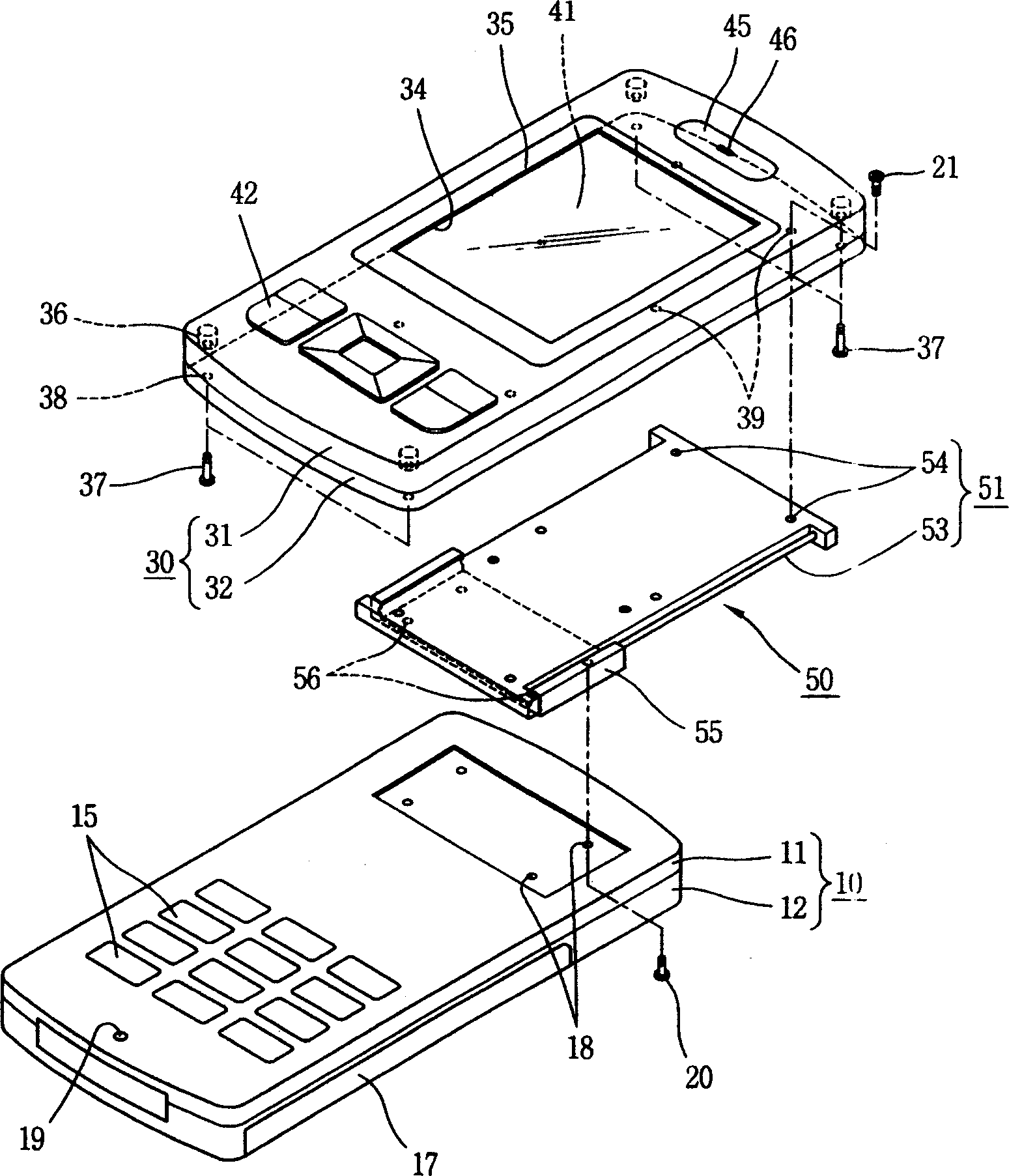
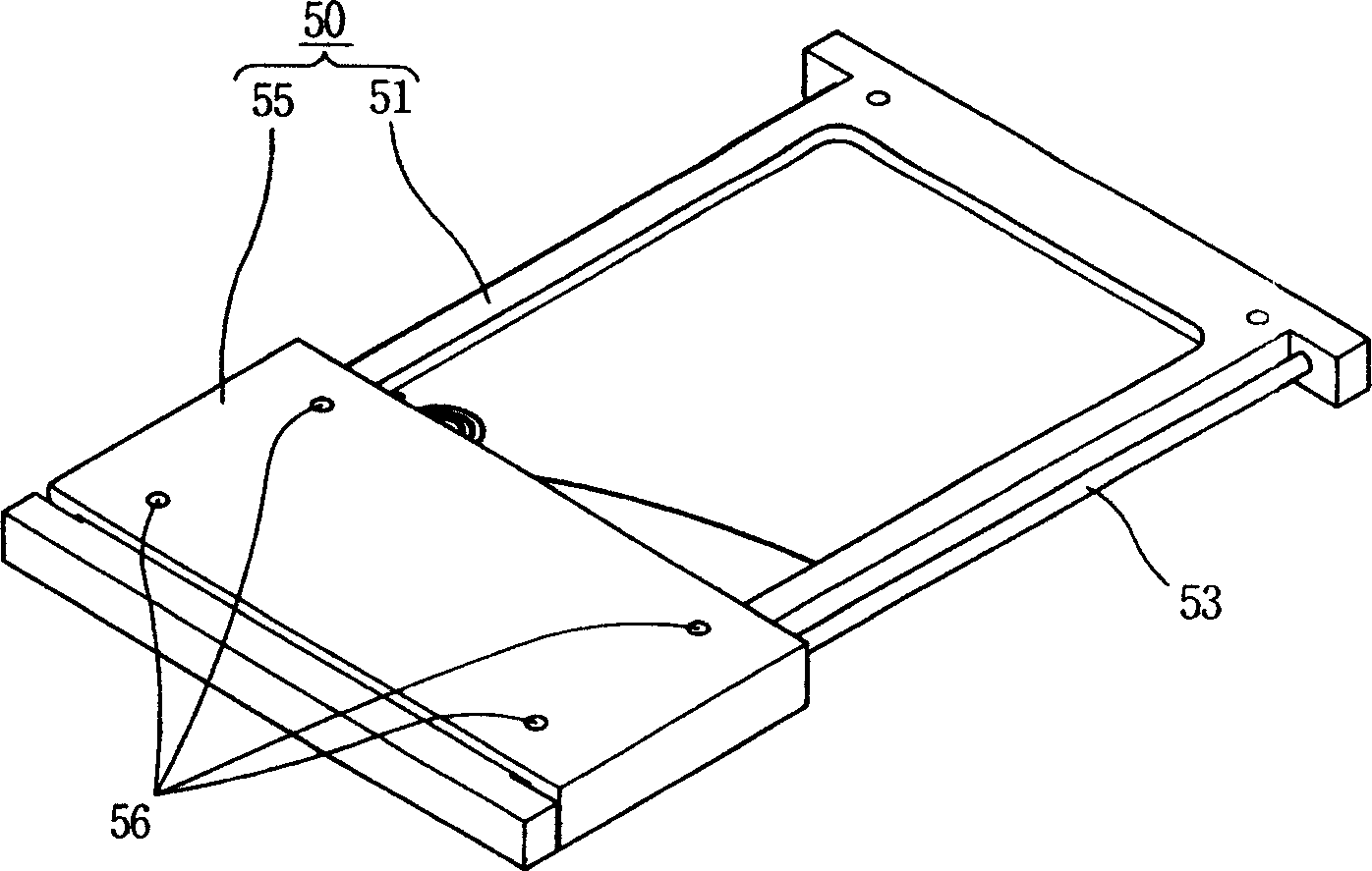
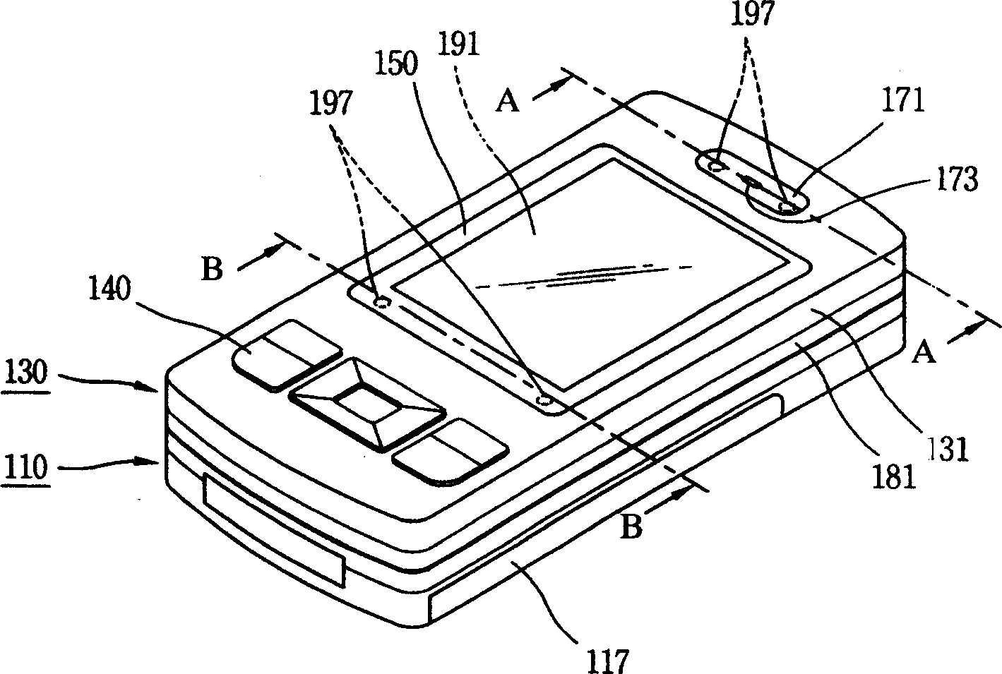
[0035] image 3 is a perspective view of a slide-type mobile communication terminal according to an embodiment of the present invention, Figure 4 yes image 3 The isolated oblique view of Figure 5 and Image 6 respectively image 3 A cross-sectional view of line A-A and B-B of the slide shown. As shown in the figure, the slide-type mobile communication terminal of the present invention includes a body portion 110 and a slide portion 130, the slide portion 130 is combined on the body portion 110 and can slide relative to the body portion 110, wherein the slide portion 130 has the following several parts: the upper shell 131 and the lower shell 181, which are opposite and contacted along the thickness direction, and the inside thereof forms an accommodating space; a plurality of connecting members, which are in the form of screws or bolts, pass through the upper shell 131, Combined with the lower case 181, the upper case 131 and the lower case 181 are combined into one bo...
PUM
 Abstract
Description
Claims
Application Information
 - R&D
- Intellectual Property
- Life Sciences
- Materials
- Tech Scout
- Unparalleled Data Quality
- Higher Quality Content
- 60% Fewer Hallucinations
Browse by: Latest US Patents, China's latest patents, Technical Efficacy Thesaurus, Application Domain, Technology Topic, Popular Technical Reports.
© 2025 PatSnap. All rights reserved.Legal|Privacy policy|Modern Slavery Act Transparency Statement|Sitemap|About US| Contact US: help@patsnap.com