Calender

A technology of a calender and a calender roll, which is applied in the field of calenders and can solve problems such as the inability to use a movable wheelbase and the like

Inactive Publication Date: 2007-01-17
METSO PAPER INC
View PDF1 Cites 1 Cited by
  • Summary
  • Abstract
  • Description
  • Claims
  • Application Information

AI Technical Summary

Problems solved by technology

In this construction, a particular problem is the impossibility of using a movable wheelbase, since the application must direct the moment in two directions

Method used


Image

  • Calender
  • Calender
  • Calender

Examples


Embodiment Construction

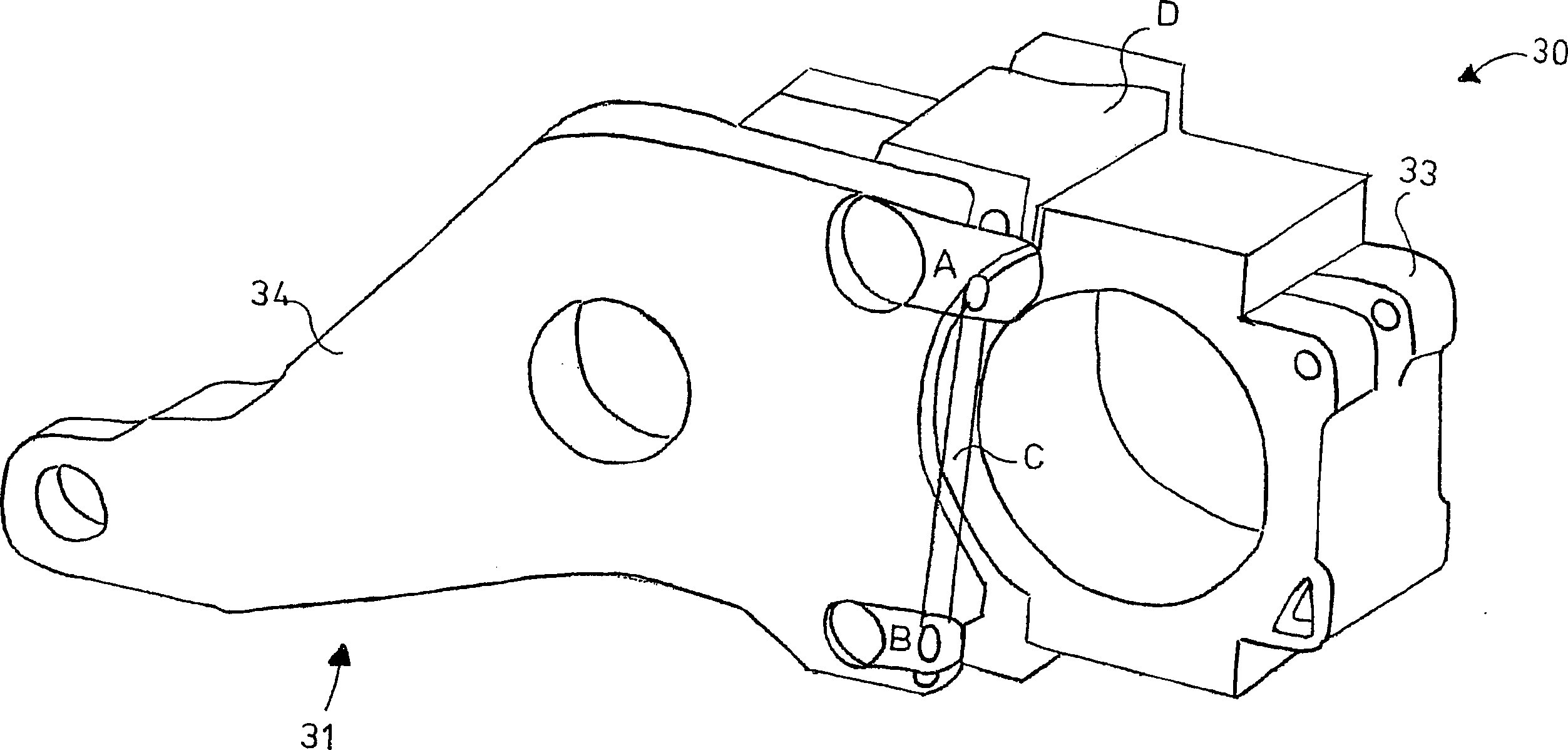
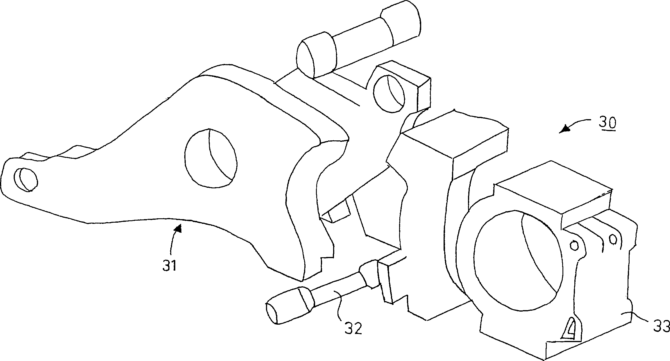
[0020] Figure 3A and Figure 3B The connection of the sliding element 30 to the rotary lever 31, which acts in the required linear movement during the staggered movement of the rollers, is shown. The linear movement is effected by hydraulics or, for example, screw jacks. On the sliding contact surface, suitable sliding bearing materials can be used between the sliding part 30 and the lever 31, such as bronze bearings, mixed metal materials and the like. Figure 3A and Figure 3B As shown, it is obvious that the sliding member 30 and the lever 31 associated with the rollers in the multi-roll calender are connected to each other, and the eccentric shaft 34 is installed in such a way that they can rotate up and down, Simultaneously, the engagement member 32 disengaged from the lever 31 moves. The roll box 33 is connected to the joint member 32, and the roll shaft (not shown) moves in the direction of the roll nip correspondingly, and the staggered stacking action required by t...


PUM


Abstract

The invention relates to a calender. This calender comprises at least three calender rollers and at least one of the calender rollers' bearing center can deviate from the routes of other calender rollers to make this deviated roller oppositely positioned to the other two rollers, so they can move with overlapping. This inventive calender has units (30) operating with overlapping to prevent wale barring. The units (30) has a displacement lever (31) to shift the bearing bushes (33) of overlapping rollers. They also have a section (32) to move the connecting surfaces.

Description

technical field [0001] The invention relates to a calender according to what is stated in the claims. Background technique [0002] In the prior art, among calenders with multi-roll groups, which is the most familiar among calenders, the rollers of the calender are composed of at least one group of rollers, which is the most common roller group, and the calender The components of the light-mechanical roll nip are located in the middle of two groups of rolls that overlap up and down, that is, between the hot roll and the soft roll. A multi-roll calender thus comprises a roll set of one or more, generally at least two calender rolls. In the most familiar and common multi-roll calenders in the prior art, the set of rolls is constructed in such a way that the line through the center axis midline of the last roll is straight. As far as the prior art is concerned, it is also common to place a plurality of rolls interlaced with each other in a calender roll set. The central axes ...

Claims


Application Information

Patent Timeline
Patent Type & Authority Applications(China)
IPC IPC(8): D21G1/00D21GD21G1/02
CPCD21G1/0226D21G1/0033D21G1/00D21G1/008
Inventor 米卡·奥尔科宁汉努·普利宁埃尔基·科伊武泰穆·萨里科斯基哈里·哈维斯托基莫·沃里宁凯约·拉克索宁尤哈·利尼亚埃尔基·莱诺宁米卡·凯桑拉赫蒂
Owner METSO PAPER INC
Why Eureka
Try Eureka