Vibration motor

A motor, a pair of technology, applied in the direction of electric components, casing/cover/support, control mechanical energy, etc., can solve the problem of conductive terminals prone to lateral shaking, etc., to ensure the contact margin, suppress vibration, and expand the lateral width. Effect

Inactive Publication Date: 2007-01-17
SANYO SEIMITSU
View PDF1 Cites 3 Cited by
  • Summary
  • Abstract
  • Description
  • Claims
  • Application Information

AI Technical Summary

Problems solved by technology

[0004] However, the conductive terminals are highly elastic, and the sealing ring is made of elastomer (rubber), so they respectively have unnecessary vibrations that are separated from the rotational vibration of the eccentric hammer, and lateral shaking is easy to occur on the conductive terminals.

Method used


Image

  • Vibration motor
  • Vibration motor
  • Vibration motor

Examples


Embodiment Construction

[0052] Embodiments of the present invention will be described below with reference to the accompanying drawings.

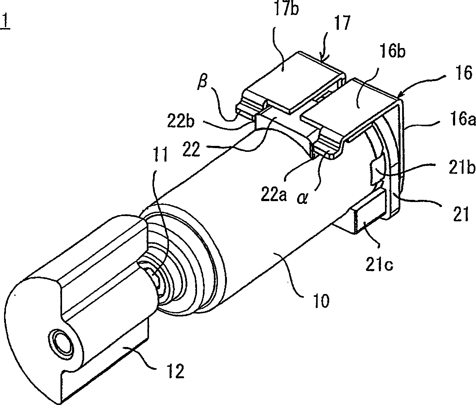
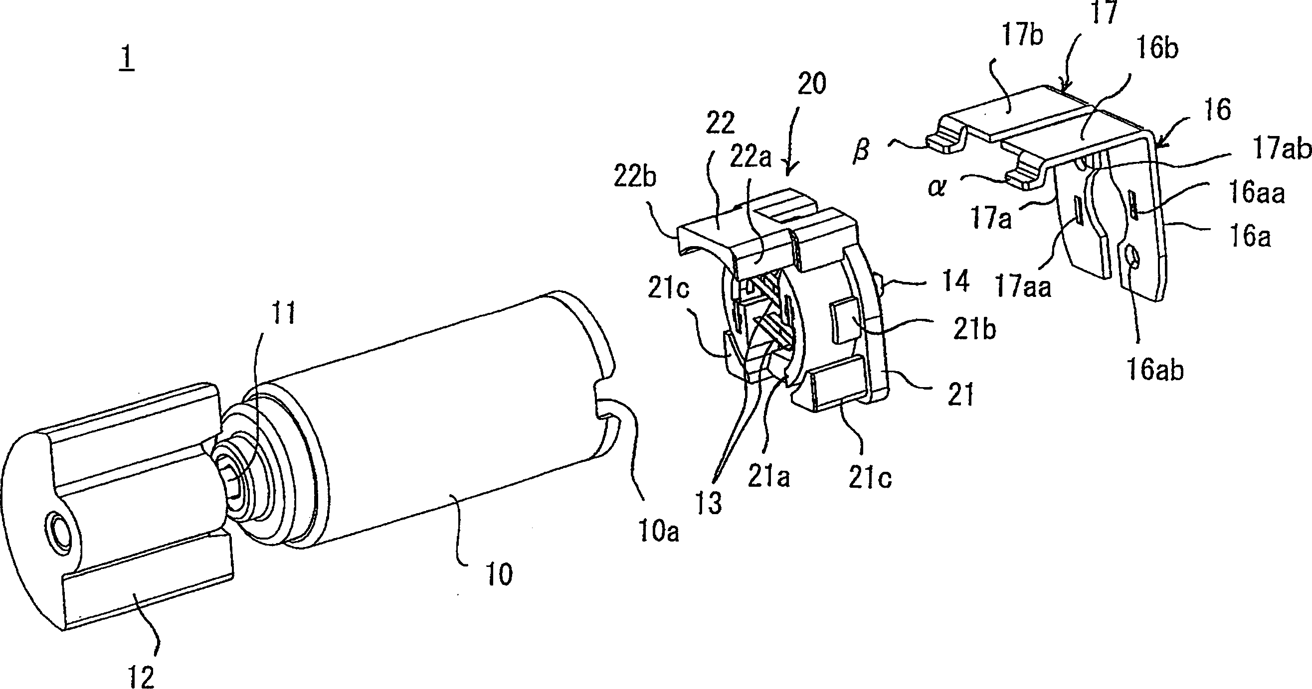
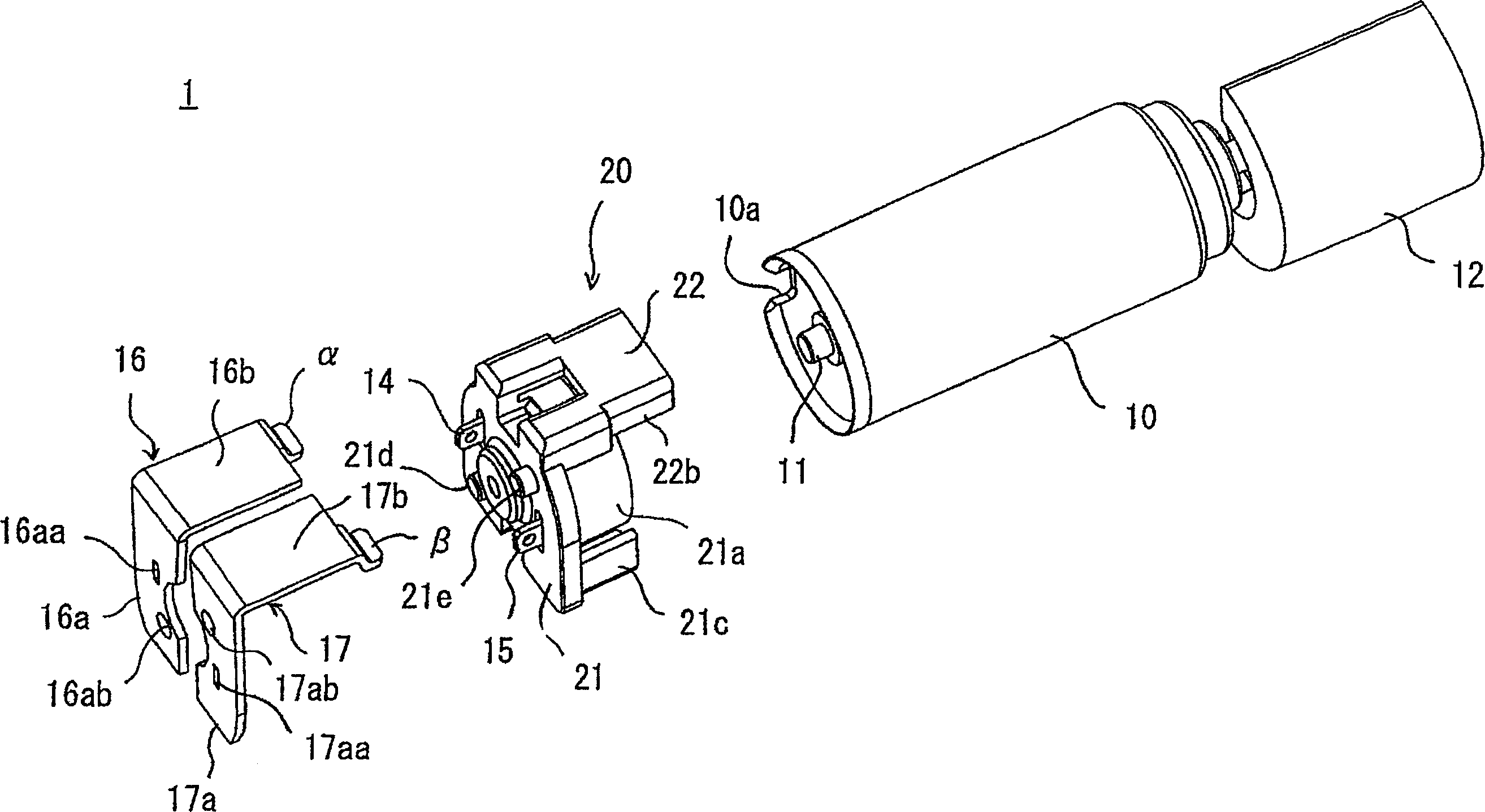
[0053] figure 1 It is an assembled perspective view showing the vibration motor related to one embodiment of the present invention. figure 2 It is an exploded perspective view partially disassembled of the above-mentioned vibration motor. image 3 from another angle figure 2 An exploded perspective view of the state shown. Figure 4 It is a perspective view showing a pair of plate-shaped conductive terminals used for the above vibration motor. Figure 5 It is a side view which shows the state which assembled the said vibration motor to a board|substrate.

[0054] The vibration motor 1 in this embodiment is configured by attaching an eccentric weight 12 to a motor shaft 11 projecting from a cylindrical motor case 10 . In the motor housing 10, a magnet (not shown) fixed on its inner peripheral surface, a rotor (not shown) fixed on the motor shaft 11, and a ro...


PUM


Abstract

A vibration motor. The use of such a vibration motor can better suppress the lateral shaking of the conductive terminal. It has a pair of motor power supply parts, a pair of plate-shaped conductive terminals, and a partition part. The motor power supply part is arranged on the end cover that closes the open end of the motor housing. The pair of plate-shaped conductive terminals include contact surfaces for contact with The contacts for power supply which are arranged on one side of the substrate and are elastically stretchable are in contact with each other, and the plate-shaped conductive terminal is connected to the motor power supply part at a position corresponding to the motor power supply part. The peripheral surface of the motor housing abuts to separate the contact surface from the peripheral surface, wherein the first contact surface as a whole has a first stopper that abuts against the first side surface of the partition portion, and the second The contact surface as a whole has a second stopper portion abutting against a second side surface of the separator which is a side surface different from the first side surface of the separator.

Description

technical field [0001] The present invention relates to a vibrating motor with an eccentric weight, in particular to an assembled vibrating motor, the plate-shaped conductive terminal can abut against the elastically shrinkable power supply contact on the side of the substrate where it is installed. Background technique [0002] Generally, conventional vibration motors have a pair of elastic conductive terminals, and such motors are assembled in a state where the conductive terminals are brought into contact with a power supply pattern on the substrate side. However, due to the vibration of the vibration motor itself and the impact of external vibrations, the elastic conductive terminals tend to shake laterally on the power supply pattern, thus hindering the electrical contact. In order to improve this defect, Japanese Patent Laid-Open No. 2002-330567 discloses a structure for improving this defect. [0003] That is, in this structure, a pair of recesses are provided on a g...

Claims


Application Information

Patent Timeline
Patent Type & Authority Applications(China)
IPC IPC(8): H02K5/22
CPCH02K7/061H02K5/225H02K5/00H02K2211/03
Inventor 高木贵弘中村将人
Owner SANYO SEIMITSU
Why Eureka
Try Eureka