Paper feed mechanism

A paper feeding mechanism and paper feeding technology, applied in printing, printing device, object supply, etc., can solve the problems of waste of recording paper 44, cost increase, etc.

Inactive Publication Date: 2007-01-24
ALPS ALPINE CO LTD
View PDF1 Cites 3 Cited by
  • Summary
  • Abstract
  • Description
  • Claims
  • Application Information

AI Technical Summary

Problems solved by technology

[0010] Therefore, from the front end portion 44a of the recording paper 44, there is a portion where at least the distance of the dimension C cannot be printed, and there is a problem that the recording paper 44 is wasted and the cost increases.

Method used


Image

  • Paper feed mechanism
  • Paper feed mechanism
  • Paper feed mechanism

Examples


Embodiment Construction

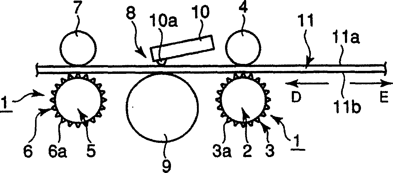
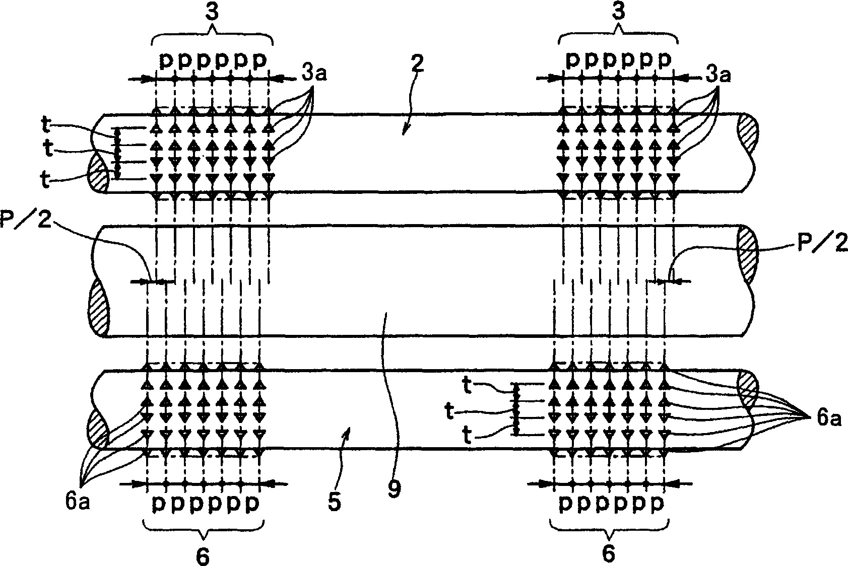
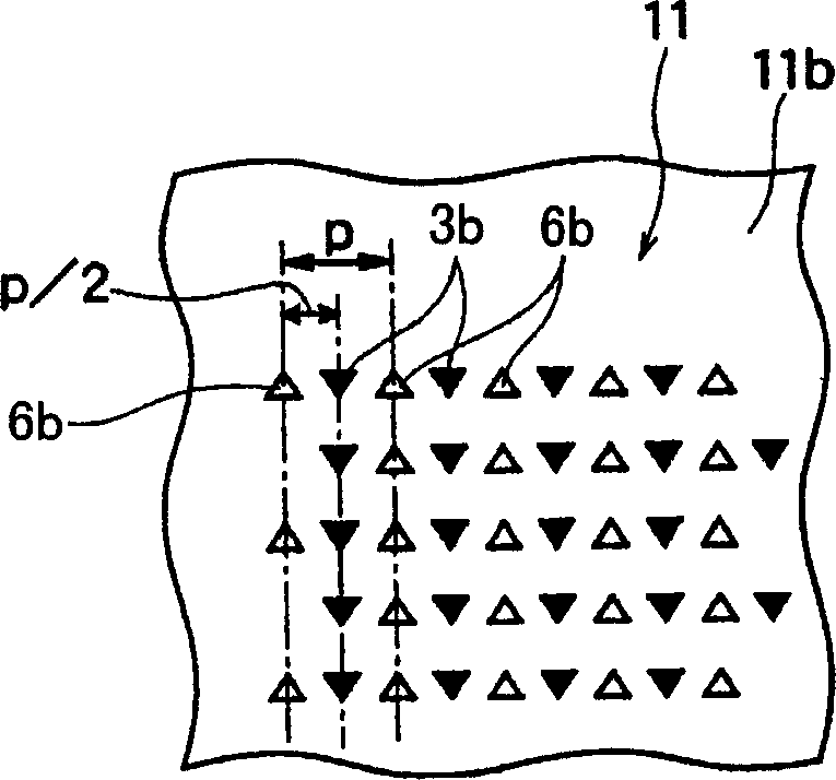
[0048] Hereinafter, the paper feeding mechanism of the present invention will be described based on the drawings. figure 1 is a schematic diagram of a printer using the paper feeding mechanism of the present invention, figure 2 It is a schematic diagram illustrating the positional relationship between the first and second paper feed rollers according to the first embodiment of the present invention, image 3 , Figure 4 It is a schematic diagram explaining the mark produced by the protrusion formed in the paper feed roller of the 1st Embodiment of this invention, Figure 5 is a schematic diagram illustrating another embodiment of the first embodiment, Image 6 is a schematic diagram illustrating the first and second paper feed rollers according to the second embodiment of the present invention, Figure 7 , Figure 8 It is a schematic diagram explaining the marks produced by the protrusions of the first and second paper feed rollers in the second embodiment, Figure 9 is...


PUM


Abstract

According to the present invention, by arranging a pair of paper feed mechanisms having a paper feed roller formed with projections at two positions on the upstream side and downstream side of the platen, it is possible to provide full-surface printing from the front end to the rear end of the recording paper. In addition, waste of recording paper can be avoided, and a pair of paper feeding mechanisms can prevent sliding of recording paper during printing. Paper feeding cylinders (2), (5) and paper feeding cylinders (2), The pressing cylinders (4), (7) of (5), utilize the recording paper (11) in the printing that the printing mechanism (8) carries out, pass the protrusion (2a) of a pair of paper feeding cylinders (2), (5) ), (5a) are transported deep into the back side (11b) of the specified size.

Description

technical field [0001] The present invention relates to a paper feed mechanism used in a printer, and relates to a paper feed mechanism capable of appropriately feeding recording paper to a printing mechanism to print a desired image and appropriately discharging the printed recording paper. Background technique [0002] The previous paper feeding mechanism 40, such as Figure 11 As shown, a metal cylindrical paper feed roller 41 is arranged, and in the longitudinal direction of the outer peripheral surface of the paper feed roller 41, a plurality of front ends protruding at an acute angle are formed at a predetermined height and pitch (pitch) dimension. The protrusion 42 has a protrusion forming portion 43 formed with a predetermined width. [0003] In addition, a pressure roller 45 capable of pressing the recording paper 44 against the paper feed roller 41 with a predetermined pressure pressure is disposed on the side opposite to the protrusion forming portion 43 . [000...

Claims


Application Information

Patent Timeline
IPC IPC(8): B41J13/02B41J11/02B41J2/01B65H5/06
Inventor 丸山贵史稻田裕二齐藤正树阿部荣文大坂威史本木善幸
Owner ALPS ALPINE CO LTD
Why Eureka
Try Eureka