Draft apparatus in spinning machine and control method of the same

The technology of a drafting device and a control method, which is applied in the field of drafting devices, can solve problems such as the inability to prevent uneven filaments and the inability to fully suppress the twisting of apron rollers, etc.

Active Publication Date: 2007-01-24
TOYOTA IND CORP
View PDF3 Cites 10 Cited by
  • Summary
  • Abstract
  • Description
  • Claims
  • Application Information

AI Technical Summary

Problems solved by technology

[0011] However, in such a configuration in which the ends of the bottom apron roller are directly held, twisting of the middle portion of the bottom apron

Method used


Image

  • Draft apparatus in spinning machine and control method of the same
  • Draft apparatus in spinning machine and control method of the same
  • Draft apparatus in spinning machine and control method of the same

Examples


Embodiment Construction

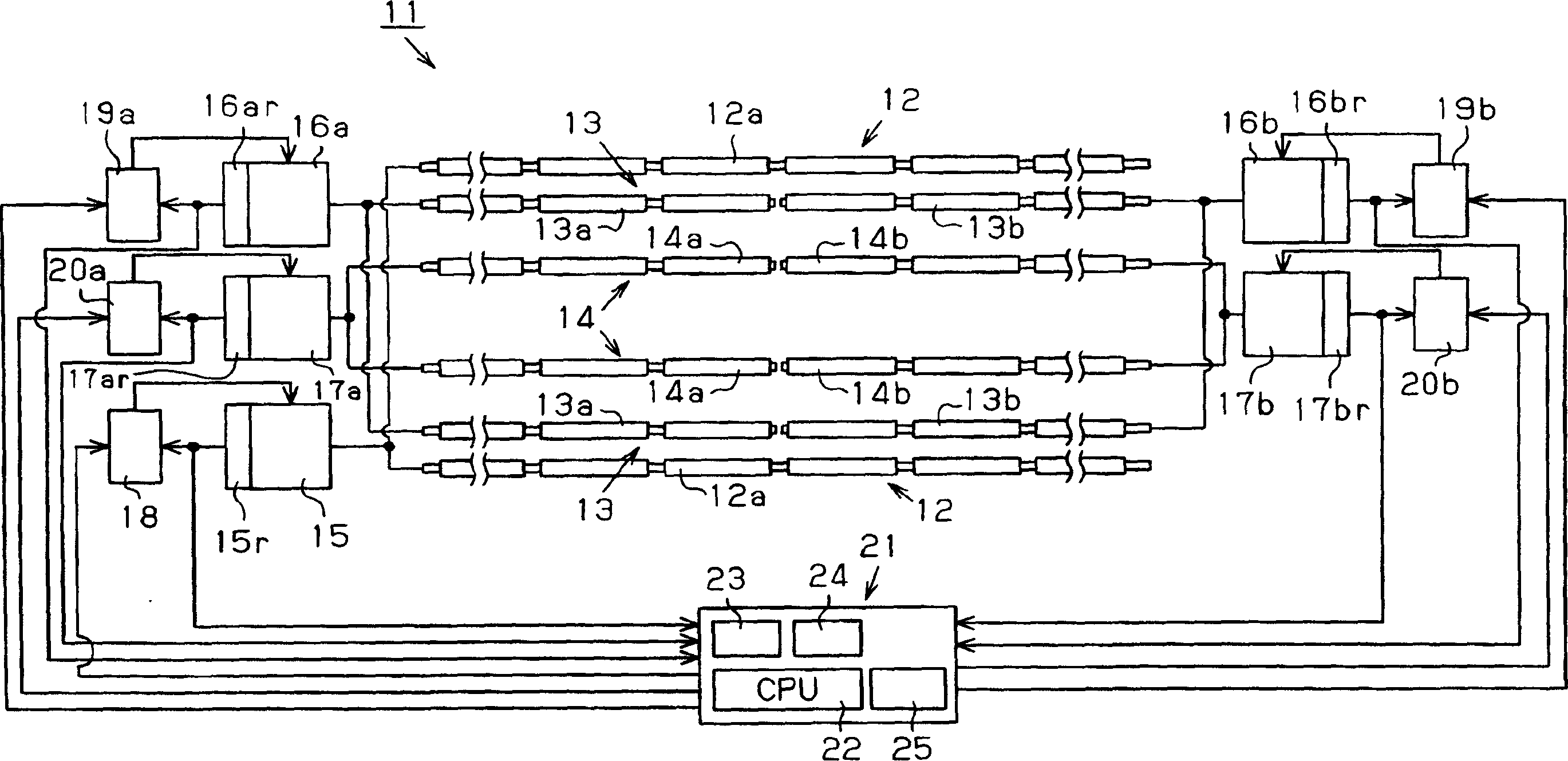
[0020] Below, according to figure 1 as well as figure 2 An embodiment in which the present invention is embodied will be described. figure 1 A drawing device 11 extending in the longitudinal direction of the machine of the ring spinning frame is shown.

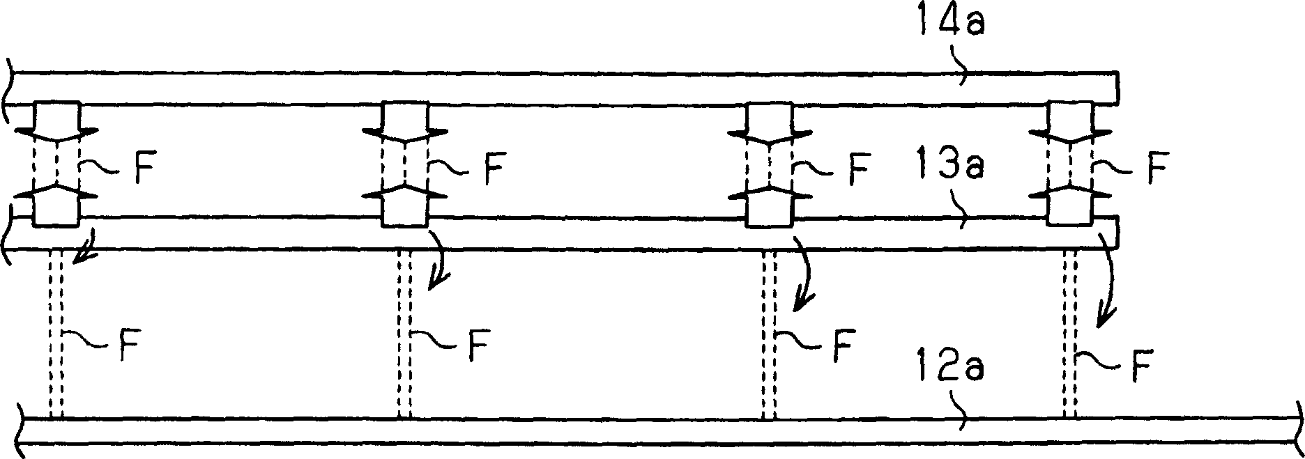
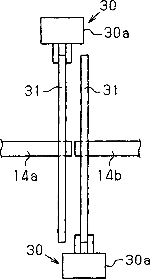
[0021] Such as figure 1 As shown, the 3-line drafting device 11 has a pair of front bottom rollers 12 extending in the longitudinal direction of the machine, a pair of middle bottom rollers 13 disposed on the inner side, and a pair of rear bottom rollers 14 disposed on the inner side. . The front bottom roller 12 is supported at a predetermined position of an unillustrated roller seat. The middle bottom roller 13 and the rear bottom roller 14 are supported by a bracket (not shown) whose position can be adjusted in the direction of clutching with respect to the front bottom roller 12 . The middle bottom roller 13 has an apron (not shown). Moreover, corresponding to each bottom roller 12-14, a front bottom roller, a middl...


PUM


Abstract

The drafting device (11) in the spinning machine has the front bottom roller (12), the middle bottom roller (13), the rear bottom roller (14), and is used to independently drive these rollers (12, 13, 14) A plurality of motors (15, 16a, 16b, 17a, 17b). The locking mechanism (21) has the function of preventing at least the rear bottom roller (14) from rotating in the normal direction during at least a predetermined period from when the spinning machine stops spinning. Therefore, it is possible to suppress excessive feeding of fibers caused by twisting of the bottom roller while the machine is stopped, thereby suppressing unevenness of the yarn when the machine is started.

Description

technical field [0001] The invention relates to a drafting device in a spinning machine and a control method thereof. In detail, the present invention relates to a drafting device having front bottom rollers, middle bottom rollers, rear bottom rollers, and motors for independently driving these rollers, and a control method thereof. Background technique [0002] A spinning machine such as a ring spinning frame or a roving frame has a machine and a plurality of spinning hammers arranged along the machine's longitudinal direction. The drafting device incorporated in such a spinning machine drives a plurality of bottom rollers at one end of the machine, such as the head. Since these bottom rollers are very long, when the spinning machine is started, a lagging twist occurs on the tail on the opposite side of the machine head. In particular, the lower apron rollers on which the aprons are wound corresponding to the respective hammers, for example, the middle lower rollers, have...

Claims


Application Information

Patent Timeline
IPC IPC(8): D01H5/22
CPCD01H1/22
Inventor 林久秋小岛直树藤井能理新美究筱崎丰
Owner TOYOTA IND CORP
Why Eureka
Try Eureka