Fuel cell exhibiting enhanced hydrogen distribution density

a fuel cell and hydrogen distribution technology, applied in the field of fuel cells, can solve the problems of difficult to increase the overall output voltage of the fuel cell, and achieve the effect of increasing the overall opening area and uniform fuel density distribution on the anode-side catalyst body

Inactive Publication Date: 2012-03-06
SEIKO INSTR INC
View PDF9 Cites 2 Cited by
  • Summary
  • Abstract
  • Description
  • Claims
  • Application Information

AI Technical Summary

Benefits of technology

[0010]The present invention has been made to solve such problems, and its object is to provide a fuel cell capable of suppressing unevenness in a hydrogen density distribution, thereby increasing an output voltage.
[0012]According to the above aspect, since the fuel is diffused in a radial shape from the center of the anode-side catalyst body, the area where the hydrogen density is uneven becomes smaller than that when the hydrogen is supplied from the introduction port provided at the edge of the anode-side catalyst body. As a result, it is possible to increase an overall output voltage of the fuel cell.
[0013]In accordance with a second aspect of the present invention, the fuel inducing portion includes a mechanism for decelerating the speed of fuel lower than that when the fuel was supplied from the outside.
[0020]According to the above aspect, since a plurality of through pores is provided, an overall opening area can be increased larger than that when only one through pore is provided. With this arrangement, the flow rate of the fuel discharged from the through pores can be decelerated to be lower than that when only one through pore is provided. Therefore, the fuel can be sprayed at substantially uniform pressure with respect to the anode-side catalyst body. Accordingly, it is possible to make the fuel density distribution on the anode-side catalyst body more uniform.
[0021]In accordance with a ninth aspect of the present invention, the fuel inducing portion includes a mechanism for decelerating the speed of fuel lower than that when the fuel was supplied from the outside.

Problems solved by technology

As a result, it is difficult to increase the overall output voltage of the fuel cell.

Method used


Image

  • Fuel cell exhibiting enhanced hydrogen distribution density
  • Fuel cell exhibiting enhanced hydrogen distribution density
  • Fuel cell exhibiting enhanced hydrogen distribution density

Examples


embodiment 1

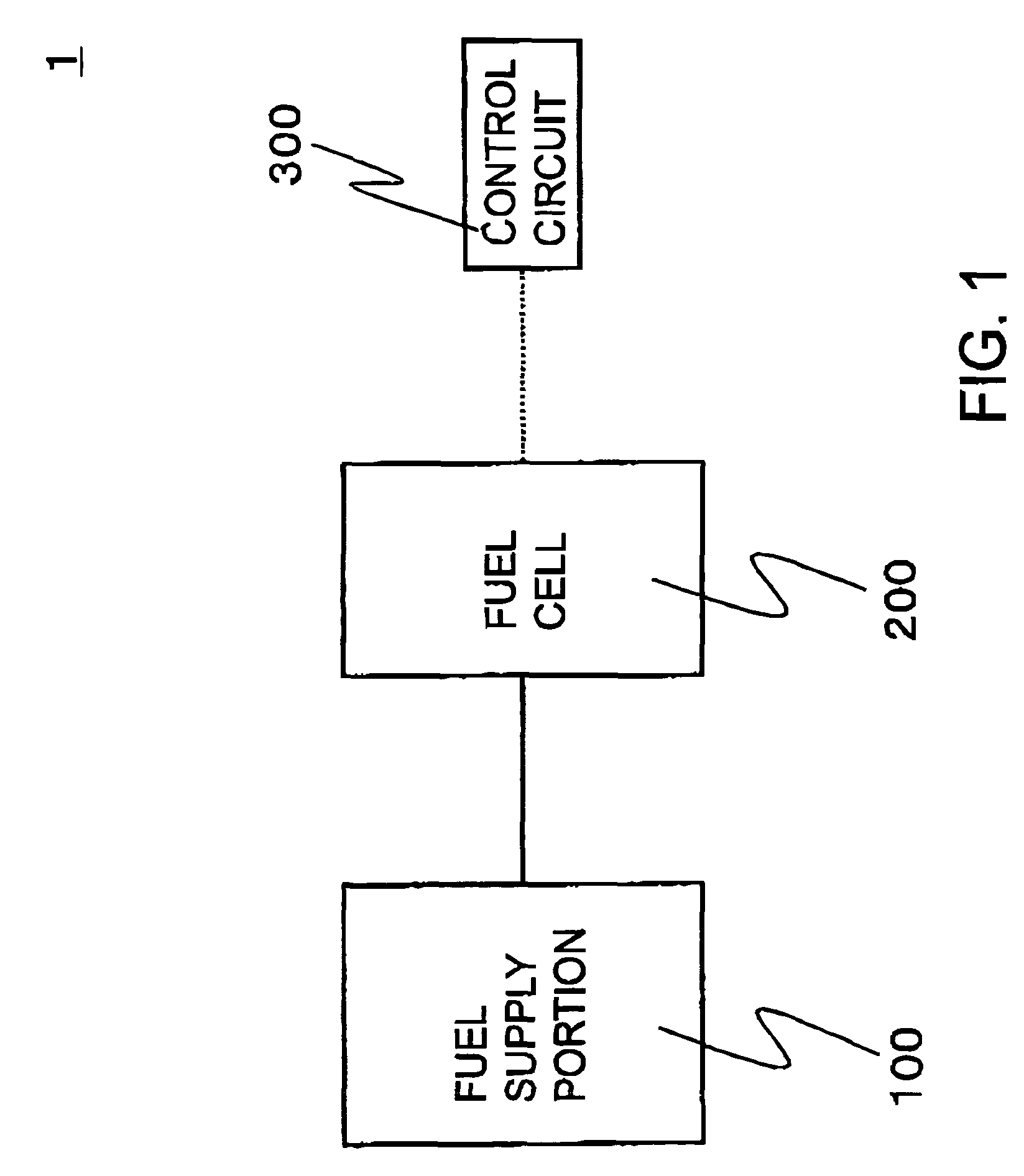
[0045]FIG. 1 shows the structure of a fuel cell system according to the present invention.

[0046]In FIG. 1, a fuel cell system 1 includes a fuel supply portion 100, a fuel cell 200, and a control circuit 300.

[0047]The fuel supply portion 100 may have any structure that can generate hydrogen, and may have a structure in which hydrogen generating substance and hydrogen generation accelerating substance are mixed with each other to discharge hydrogen. Preferably, the fuel supply portion 100 may have a structure in which sodium borohydride as hydrogen generating substance and a malic acid solution as hydrogen generation accelerating substance are mixed with each other to discharge hydrogen.

[0048]As a combination of the hydrogen generating substance and the hydrogen generation-accelerating substance, besides the above-mentioned example, the hydrogen generating substance may be any metal hydrides that can be hydrolyzed and the hydrogen generation accelerating substance may be any hydrogen ...

embodiment 2

[0145]In the fuel inducing portion of the first embodiment, hydrogen is introduced toward the center of the surface of a single anode-side catalyst body. To the contrary, in a second embodiment, hydrogen is induced toward plural locations of the surface of a single anode-side catalyst body. The second embodiment will be described in detail below.

[0146]FIG. 15 is a diagram showing the structure of an anode-side member 221A according to the second embodiment of a fuel cell of the present invention.

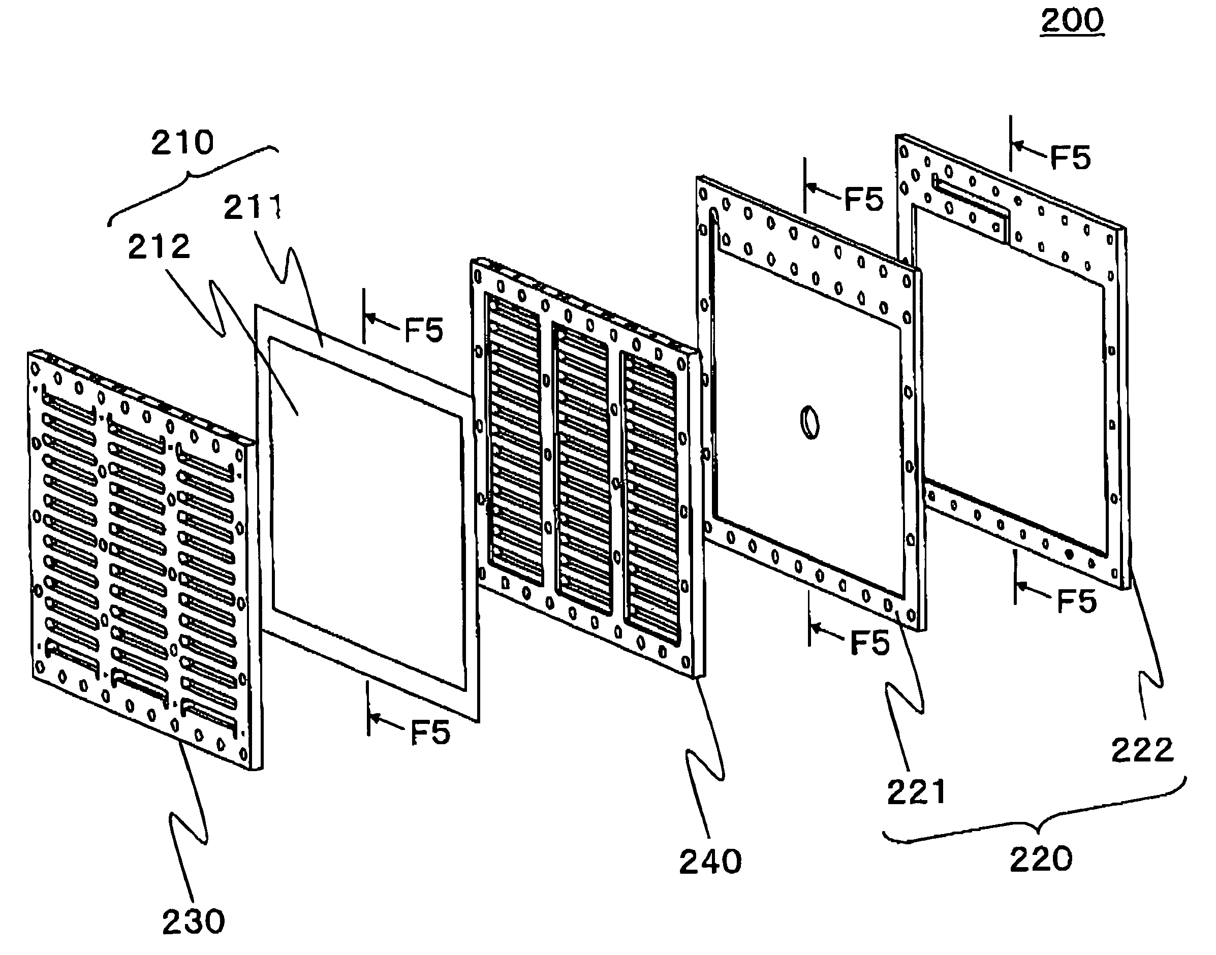
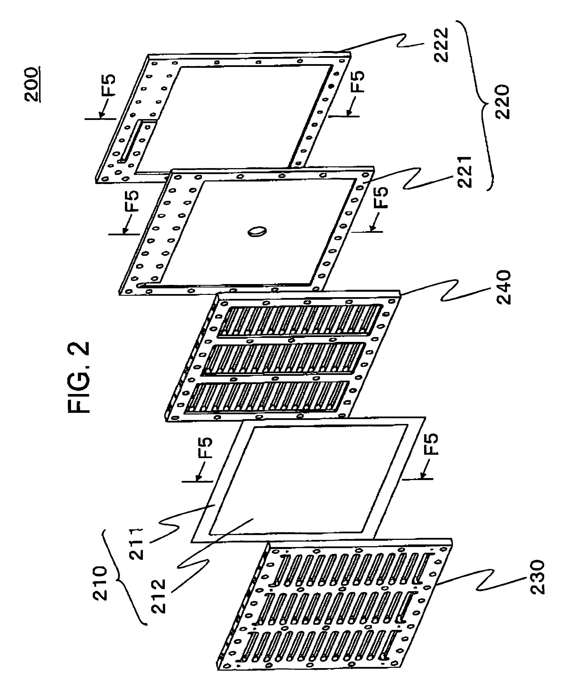
[0147]The anode-side member 221A is a modified example of the anode-side member 221 of the fuel cell 200 shown in FIG. 2. The anode-side member 221A includes a recess portion 221-1 on a side where an anode-side catalyst body is disposed. A plurality of through pores 221-4a, 221-4b, and 221-4c are formed in the recess portion 221-1.

[0148]The anode-side member 221A has a triangular surface 221-5 (polygonal surface) formed by the lines passing through the above-mentioned three through pores. In...

modified example 1

[0155]In the second embodiment, the anode-side member 221A includes the triangular surface 221-5 formed by the lines passing through the three through pores. To the contrary, in a first modified example, an anode-side member 221B has a rectangular surface 221-7 formed by the lines passing through four through pores. The first modified example will be described in detail below.

[0156]FIG. 16 is a diagram showing the structure of the anode-side member 221B according to the first modified example of the second embodiment.

[0157]The anode-side member 221B includes through pores 221-6a, 221-6b, 221-6c, and 221-6d.

[0158]In a front view of the anode-side member 221B as viewed from the cathode side, the rectangular surface 221-7 is disposed at a position overlapping the surface of the anode-side catalyst body.

[0159]In this modified example, the above-mentioned four through pores are arranged such that a normal line of the anode-side catalyst body surface passing through the center (the cente...


PUM

PropertyMeasurementUnit
sizeaaaaaaaaaa
depthaaaaaaaaaa
depthaaaaaaaaaa

Abstract

This invention provides a fuel battery comprising a solid polymer electrolyte membrane, an anode-side catalyst body and a cathode-side catalyst body disposed respectively on both sides of the solid polymer electrolyte membrane, and a fuel guide part in which the anode-side catalyst body is disposed opposite to the anode-side catalyst body on the opposite side where the anode-side catalyst body faces the solid polymer electrolyte membrane and which guides a fuel which has been externally supplied toward the center of the face of the anode-side catalyst body.

Description

CROSS-REFERENCE TO RELATED APPLICATION[0001]This application is a U.S. national stage application of International Application No. PCT / JP2006 / 319928, filed Oct. 5, 2006, claiming a priority date of Oct. 7, 2005, and published in a non-English language.TECHNICAL FIELD[0002]The present invention relates to a fuel cell having a solid polymer electrolyte membrane and an anode-side catalyst body and a cathode-side catalyst body disposed on opposite surfaces of the solid polymer electrolyte membrane.BACKGROUND ART[0003]A fuel cell system is known, particularly, in which a membrane electrode assembly (hereinafter, referred to as MEA) generates electricity from hydrogen induced to an anode side of a fuel cell and oxygen induced to a cathode side thereof.[0004]In the past, in the fuel cell system, hydrogen was supplied to a flow path formed on a separator.[0005]However, in such a flow path structure, a hydrogen density distribution is formed from the vicinity of an introduction port through ...

Claims


Application Information

Patent Timeline
Patent Type & Authority Patents(United States)
IPC IPC(8): H01M8/04H01M8/24
CPCH01M8/0258H01M8/04089H01M8/1002H01M8/241H01M8/0265Y02E60/521H01M8/1007Y02E60/50H01M8/2418
Inventor OZAKI, TORUIWASAKI, FUMIHARUYUZURIHARA, KAZUTAKATAMACHI, TSUNEAKISARATA, TAKAFUMIYANASE, NORIMASA
Owner SEIKO INSTR INC
Why Eureka
Try Eureka