
Integrated machine room

A machine room and column technology, which is applied to special buildings, small buildings, building components, etc., can solve the problems of on-site geographical environment restrictions, inconvenient transportation, etc., and achieve the effect of reducing transportation difficulty, shortening construction period, and reducing transportation costs

Inactive Publication Date: 2017-05-10
SICHUAN ANNENG ENERGY TECH CO LTD
View PDF6 Cites 2 Cited by
  • Summary
  • Abstract
  • Description
  • Claims
  • Application Information

AI Technical Summary

Problems solved by technology

[0003] In order to solve the defects that the existing container-type machine room is inconvenient to be welded and transported as a whole, and the installation is limited by the local environment of the site, the present invention provides an integrated machine room

Method used


Image

  • Integrated machine room
  • Integrated machine room
  • Integrated machine room

Examples


Embodiment 1

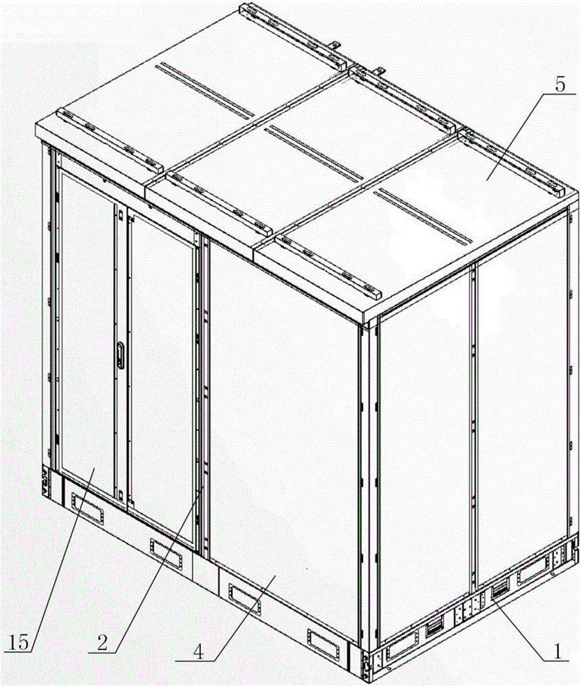
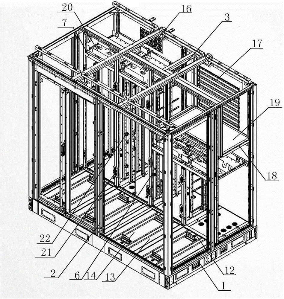
[0037] An integrated machine room, comprising a base 1, a plurality of external columns A2 are arranged on the base 1, a top frame 3 is connected to the upper end of the external column A2, a wall panel 4 is installed between adjacent external columns A2, and a top frame 3 is provided There is a top cover 5, and a plurality of internal columns B6 are arranged on the base 1, and installation frames 7 for dividing the machine room into each cabin are arranged between the internal columns B6. The frame 3, the external column A2 and the wall panel 4, the top frame 3 and the top cover 5, the base 1 and the internal column B6 are all detachably connected.

Embodiment 2

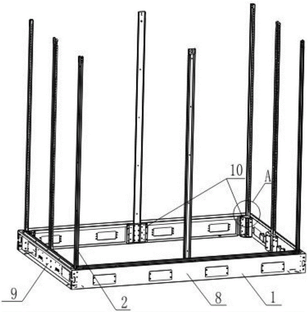
[0039] In this embodiment, on the basis of Embodiment 1, the base 1 includes a long frame 8 and a short frame 9, and the long frame 8 and the short frame 9 form a frame structure through screw connections, and the long frame 8 and the short frame The frame 9 and the four frame corners of the base 1 are screwed with connectors 10, and the connectors 10 are provided with slots 11 for the external column A2 to pass through.

Embodiment 3

[0041] In this embodiment, on the basis of Embodiment 2, the short frames 9 on both sides are connected with an intermediate crossbeam 12 through screw threads, and the intermediate crossbeam 12 and the long frame 8 are connected with multiple rear beams 13 through threads, and the intermediate crossbeam 12 The channel formed with the rear beam 13 is provided with a bottom plate A14.


PUM


Abstract

The invention provides an integrated machine room. The integrated machine room comprises a base, wherein the base is provided with a plurality of outer stand columns A; the upper ends of the outer stand columns A are connected with a top frame; a wall board is clamped between the adjacent outer stand columns A; a top cover is arranged on the top frame; a plurality of inner stand columns B are further arranged on the base; a mounting frame for separating the machine room into cabin bodies is arranged between the adjacent inner stand columns B; and the outer stand columns A and the base, the outer stand columns A and the top frame, the outer stand columns A and the wall board, the top frame and the top cover, and the base and the inner stand columns B are detachably connected. According to the integrated machine room provided by the invention, the whole machine room is divided into a plurality of small unit modules and the small unit modules only need to be simply assembled on site, so that the construction period is greatly shortened and pollution to the environment by building garbage is also reduced. In the transportation process, only all the unit modules need to be transported, so that the transportation difficulty and transportation cost of the machine room are greatly reduced, and influences on construction of the machine room, caused by a region environment, are also reduced.

Description

technical field [0001] The invention relates to a machine room, in particular to an integrated machine room. Background technique [0002] With the continuous development of society, information is particularly important to each of us, but it has become more and more difficult to build a traditional computer room in the city, and we are facing more challenges, such as property coordination, urban management, and household investment and demolition; and There are difficulties in building stations in remote mountainous areas, such as impassable roads, difficulties in fetching water and electricity, and high transportation costs of building materials. The civil structure computer room is a manual operation, the construction period is long, the construction efficiency is low, and it is difficult to keep up with the network laying speed. Moreover, the construction of the civil structure computer room will also generate dust, noise and non-recyclable construction waste, which affe...

Claims


Application Information

Patent Timeline
IPC IPC(8): E04H1/12E04B1/343E04B1/68
CPCE04H1/1238E04B1/34326E04B1/6801
Inventor 李俊锋徐勇
Owner SICHUAN ANNENG ENERGY TECH CO LTD
Learn More