Superposition beam structure for prefabricated bridge surface plate and steel beam close combination

A bridge deck and composite beam technology, applied in bridges, bridge parts, bridge construction, etc., can solve the problems of intermittent and discontinuous shear force transmission, stress concentration, and poor connection strength, so as to improve the longitudinal distribution length of load and improve Stress state, increase the effect of spanning ability

Active Publication Date: 2007-01-24
SHANGHAI URBAN CONSTR DESIGN RES INST GRP CO LTD
View PDF0 Cites 8 Cited by
  • Summary
  • Abstract
  • Description
  • Claims
  • Application Information

AI Technical Summary

Problems solved by technology

But the disadvantages of this technology are: the connection between the bridge deck and the cantilever slab depends on a short section of concrete poured later, and the connection strength is poor; Deformation; temporary support is required during construction, which increases construction costs
[0004] 2) Two types of prefabricated bridge deck technologies with cantilevers have been developed abroad, but both have certain defects and limitations
There are two obvious defects in this prior art: a) the shear force transmission between the concrete bridge deck and the steel girder is discontinuous; b) in the non-synthetic area, there is a weak line Void zone 22, where corrosion of steel beams is prone to occur and difficult to repair and maintain
Although this technology can overcome the two defects of the aforementioned prior art, it has produced other defects, such as: a) the construction and quality control of injection cement mortar can only be carried out under invisible conditions; During the installation of the bridge deck, the slab section at the shear groove is relatively weak and has stress concentration; c) the sealing requirements are very high; d) there is no steel connection between the precast concrete bridge deck blocks
[0007] In addition, no technology has been developed at home and abroad that can perform prestressed steel cable tensioning on long-span concrete bridge decks in the prefabrication field, so as to avoid the additional internal force of steel components caused by on-site prestressed steel cable tensioning

Method used


Image

  • Superposition beam structure for prefabricated bridge surface plate and steel beam close combination
  • Superposition beam structure for prefabricated bridge surface plate and steel beam close combination
  • Superposition beam structure for prefabricated bridge surface plate and steel beam close combination

Examples


Embodiment Construction

[0051] The embodiments of the present invention will be described in further detail below in conjunction with the accompanying drawings, but the present embodiments are not intended to limit the present invention, and any similar structures and similar changes of the present invention should be included in the protection scope of the present invention.

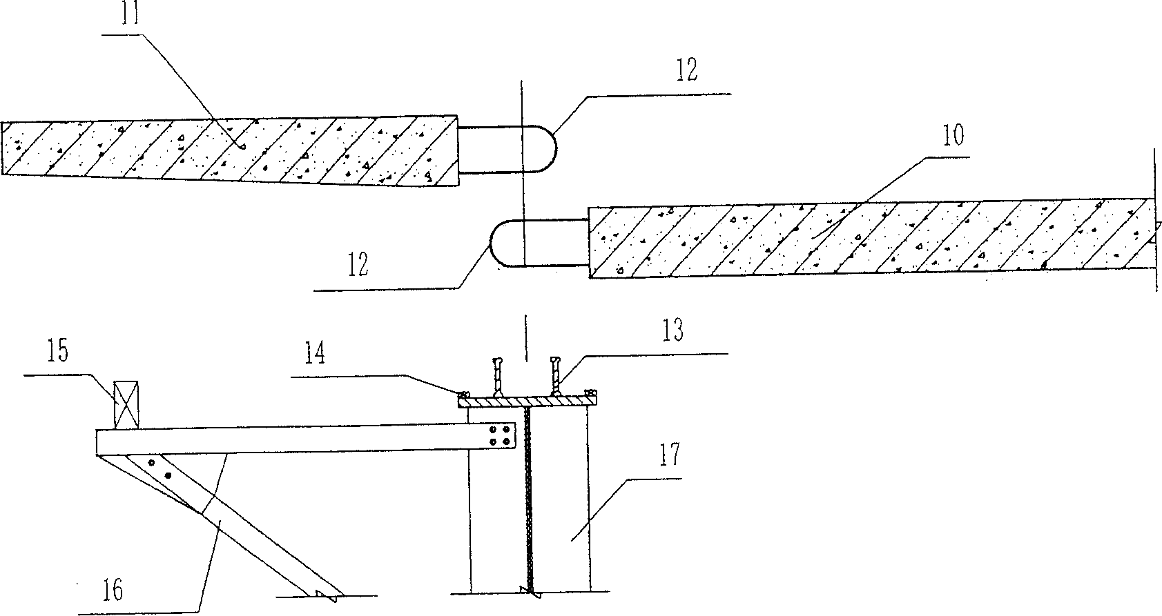
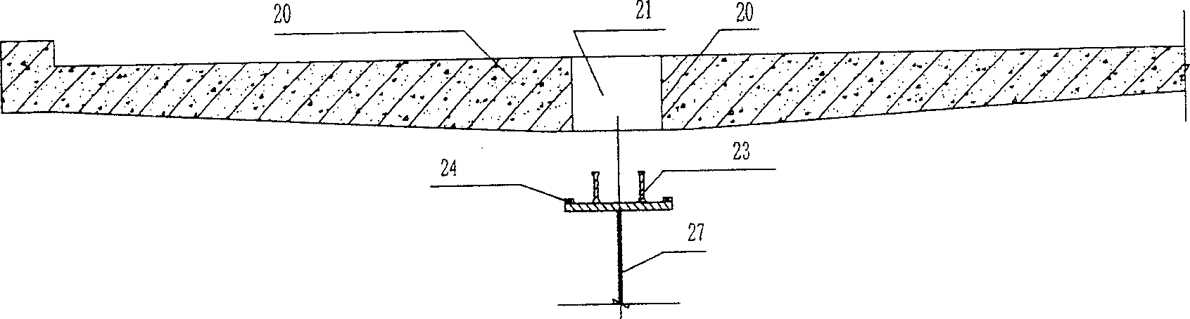
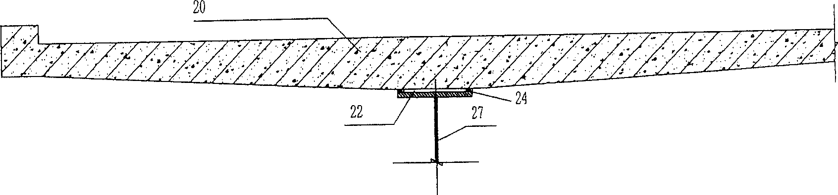
[0052] In this specification, let the edge of the plate perpendicular to the direction of the bridge body be the end, let the edge of the plate parallel to the direction of the bridge body be the wing, and assume that pouring a prefabricated concrete bridge deck on the steel girder is the first phase of on-site pouring. Adjacent bridge decks that have been poured on steel girders are connected together for the second phase of in-situ pouring. see Figure 5 , as shown in 6, the composite beam structure in which the prefabricated bridge deck and the steel beam are closely combined in the present invention includes:

[0053] Pre...


PUM


Abstract

A prefabricated bridge deck and steel beam tight coupling composite beam structure includes precast concrete bridge deck assembly and steel beam assembly. Said precast concrete bridge deck assembly has precast concrete bridge deck, end surface loop type steel reinforcement, bottom surface shear resistant slot, and bottom surface shear resistant unit. Said steel beam assembly has upright steel beam, steel beam top flange plate, integrated steel plate side formwork, shear resistant unit, integrated steel mesh end mould, said steel beam top flange plate shear resistant unit intersect polymerizing with said bridge slab bottom surface shear resistant unit..Said invention is suitable for prefabricated bridge deck with overhung tight coupling with steel beam, but also capable of having tightwire hole, wherein capable of setting bridge floor prestressed cable tensile in factory for prefabrication.

Description

technical field [0001] The invention relates to a composite beam structure for a bridge, in particular to a composite steel-concrete composite beam structure which is jointly stressed through the combination of a shear device on a steel beam and a concrete bridge deck, and especially relates to a composite beam structure with a cantilever The composite beam structure of the prefabricated bridge deck and steel girder compact structure. Background technique [0002] In composite steel-concrete composite beams, because of the large additional internal force caused by the shrinkage and creep of pure cast-in-place concrete bridge decks, and the need for a large number of formwork, precast concrete bridge deck technology is widely used. Precast concrete bridge deck technology is to erect the precast concrete bridge deck on the steel girder, pour a small amount of concrete on site to make the shear device on the steel girder, the shear groove on the precast concrete bridge deck, th...

Claims


Application Information

Patent Timeline
Patent Type & Authority Applications(China)
IPC IPC(8): E01D19/12E01D21/00E04B1/38
Inventor 候引程
Owner SHANGHAI URBAN CONSTR DESIGN RES INST GRP CO LTD
Why Eureka
Try Eureka